coolrob
Newbie level 4
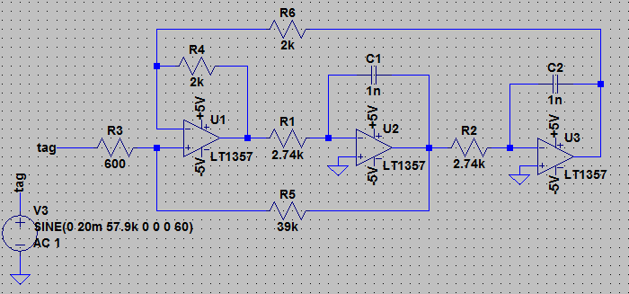
I have to design a band-pass active filter which will be a part of receiver of acousto-magnetic EAS system. Actually I'm doing a simulations using LTSpice and try to select a few opamps for further prototyping. It works fine, but I have a few questions. The key parameters are the following:
- f0 = 58kHz
- Q: ~10-50 tunable
- gain: ~20-40dB tunable
- input signal: from receiver antenna (LC network etc.) 1...50mV with a lot of mess, especially interferences from neighbouring SMPS etc.
- load: antialiasing filter and ADC in microcontroller
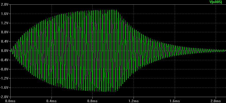
Goal: Detection of pure 58kHz signal from tag. It will be finally done using DSP in a microcontroller. A weaker signal
My questions:
1) How to select the GBW of opamp for state variable topology? Is the rule 100*f0*gain is correct? So 100*58kHz*100V/V = 580MHz? :| Should I reduce gain?
2) How to bring the rule above together with the following advice:
4) Does the type of power supply (single or symmetrical) do matter?
5) Can I use a digital potentiometer for adjusting filter parameters? Do you have any advice about that? Small capacitance?
- f0 = 58kHz
- Q: ~10-50 tunable
- gain: ~20-40dB tunable
- input signal: from receiver antenna (LC network etc.) 1...50mV with a lot of mess, especially interferences from neighbouring SMPS etc.
- load: antialiasing filter and ADC in microcontroller
Goal: Detection of pure 58kHz signal from tag. It will be finally done using DSP in a microcontroller. A weaker signal
My questions:
1) How to select the GBW of opamp for state variable topology? Is the rule 100*f0*gain is correct? So 100*58kHz*100V/V = 580MHz? :| Should I reduce gain?
2) How to bring the rule above together with the following advice:
3) How about noise in opamp, should I care about it in this application? On the one hand I have high gain but on the other this is not a precision dc or audio application."unlike the single op amp architectures, the open loop gain (3Q) need only be slightly higher than the filter's output gain (Q), and the low-pass gain is Q, which reduces the requirements on the op amps GBW"
https://www.maximintegrated.com/en/app-notes/index.mvp/id/1762
4) Does the type of power supply (single or symmetrical) do matter?
5) Can I use a digital potentiometer for adjusting filter parameters? Do you have any advice about that? Small capacitance?