Continue to Site

Welcome to EDAboard.com

Welcome to our site! EDAboard.com is an international Electronics Discussion Forum focused on EDA software, circuits, schematics, books, theory, papers, asic, pld, 8051, DSP, Network, RF, Analog Design, PCB, Service Manuals... and a whole lot more! To participate you need to register. Registration is free. Click here to register now.

Simulate the TI's Demo board PMP7188 in LTspice

Status
Not open for further replies.

gwdbsuccess

Junior Member level 2
Joined
Nov 7, 2016
Messages
20
Helped
1
Reputation
2
Reaction score
1
Trophy points
3
Activity points
148
Basically,it can work.
But I discover that the value of Vin is digger than 36(typ Vin ESD) in the beginning.
t1.JPG

Theoretically, Vin should be clamped between 30~40.
It is impossible that Vin>40.
Is it a error of LTspice???
t2.JPG
plz help me with this problem.m(_ _)m

View attachment PMP7188.rar
 

Hi,

in the given picture I see the "5mA" condition. Did you take care about this?
How do you limit this current?

Klaus
 

KlausST

Sorry!
I didn't notice it!

I don't know what it mean.
I use resistor(R1&R2) to limit the current.
t4.JPG
 

Due to missing components, the circuit can't be simulated. If you post a simulation circuit, you should add all files that are not contained in a recent LTspice distribution.

I might be either a model fault (Z-diode missing or inappropriately modeled) or a LTSpice problem.

5 mA is a maximum rating for continuous current. The Z-diode should still have a clamping effect at higher currents.

- - - Updated - - -

I reviewed your circuit a second time. Looks like LM5021 misses a ground pin.

- - - Updated - - -

Second comment. I see that the LM5021 model uses global ground node 0. Should work, bad practice though.

But there's no Z-diode model in the subcircuit. You may want to add it externally.
 
FvM
Sorry, it's my false that I didn't check the files.
This is a new files I have checked.
View attachment PMP7188.rar

the LM5021 model has only just 7 pins.
I will simulated in TINA-TI again.
If I have any information or solution, I will reply here.

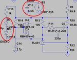
In order to simulate optocoupler, I use Diodes and behavioral current sources as shown below.
t5.png
 
Last edited:

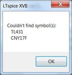
Still missing symbols

message.jpg

If you post a simulation circuit, you should add all files that are not contained in a recent LTspice distribution.
Means, you unpack the archive, open the *.asc file and start the simulation with a standard Ltspice version.
 

Besides the missing Z-diode in LM5021 model, which can be easily added, what's your particular question?
 

My question is:
Because Cvin(C7) should be shorted to GND, the Vin should be close to 0 in the beginning.
The Z-diode shouldn't be a major cause this result.(Maybe I'm wrong)
 

Status
Not open for further replies.

Similar threads

Part and Inventory Search

Welcome to EDABoard.com

Sponsor

Back
Top