Continue to Site

Welcome to EDAboard.com

Welcome to our site! EDAboard.com is an international Electronics Discussion Forum focused on EDA software, circuits, schematics, books, theory, papers, asic, pld, 8051, DSP, Network, RF, Analog Design, PCB, Service Manuals... and a whole lot more! To participate you need to register. Registration is free. Click here to register now.

multiplexing an array of sensors using a FPGA

Status
Not open for further replies.

gpascu

Newbie level 3
Joined
Dec 5, 2014
Messages
3
Helped
0
Reputation
0
Reaction score
0
Trophy points
1
Location
plymouth uk
Activity points
56
Hello everybody my project is to multiplexing an 4x4 up to 32x32 array of biosensors. My part is to design and build the electronic circuit. First taught was to use an FPGA platform and I already have an ALTERA DEO-NANO Cyclone 4 board for design test and evaluate my circuit. my knowledge of VHDL are not high and if every one can give me any advice or to put me into a direction will be very welcome. If another option to be used, like microcontrroler are much suitable for this I'll be happy to change. any site, book, related on my project will be a great help for me. Thanks.
 

You need to be more specific. Do yo want us to design the whole thing for you? Do you want a reference on VHDL? Do you have a question about interfacing your ill-defined "biosensors"? Do want to know about analog multiplexers?

Draw a block diagram of your system, break it into pieces. This will help you figure out where you need help.
 

Hi,

There are sensors with analog output...they usually can not be multiplexed with a (digital) FPGA.
There are sensors with a many different digital interfaces. Some may be multiplexed with an FPGA some not.

Klaus
 

There are two problems:
1.) how do you get the data in? The board has a 200ksps, 8 channel ADC and then a larger number of GPIO. For the 4x4 case, you could have an external board with analog switches/buffers/filters to provide the input to the 8 input ADC. That might be enough to start further work.
2.) how do you get the data out? I couldn't determine if you could use the USB as a data port in a high-speed mode, or if you were limited to using in a JTAG/UART mode.
 

Hello again! First, I want to thanks to all for answers to my post. I can give more details about my project at this point:
It is to design, build and test an array of graphene-based biosensors. Technology is based on back gated JFET and will be 5 or 6 different type of them depending on the type of biomarkers to be measured. I considered 8 rows of sensors in case the number of biomarkers grow, each one of the sensors having S connected to a common ground and each row of sensors have D connected together and fed by a selector/demux, one at a time.
The gates will be connected to the sample. Each sensors will have a number of 3 or 4 outputs to be sure that we will have at least one a valid reading from each sensor. The sensors are to be built in the uni lab and probably not to have them soon, so for testing and presentation I probably build an array of resistors. The level of signal delivered by sensors will be very low µA or lower and possible amplification required. An image of a sensor is presented below:
sensor.png
The outputs of each sensors (on columns) will fed a comparator and once I have, a valid value is to move to next column. Next, any valid value of measurement will be selected and using a DAC is transform in binary, for communication between the sensors array and display I consider UART/USART.
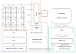
All the “digital” parts of the circuit, counter, demux, mux is to be implemented on FPGA and DAC, parallel to serial, UART/USART, filtering (if it must) is to be done using an ARM microcontroller, I studied STM as a module. For amplifying, I will use high performance OP-AMPS, with a very low level of noise, only if necessary.
For displaying, I will use LabVIEW or MATLAB, the results must be in form of a graph, and not sure if is possible to use any of these programs above at this point. The circuitry for the displaying, serial to parallel, ADC will be done on breadboard only optional to do a PCB. A block diagram is presented below:
block diagram.png
Any suggestion, advice, hint will be welcome. Thank you!
 

I'm still not quite understanding this. First of all I don't understand the bit about comparators, particularly the sentence :
"The outputs of each sensors (on columns) will fed a comparator and once I have, a valid value is to move to next column. "
Are those things labeled "C1", "C2" comparators? With four inputs? And then you take the comparator outputs and apply them, through a mux, to the input of a DAC? Or do you really mean ADC?

Regardless, I think you want to replace your counter/demux arrangement with a state machine. And probably a lot of this design should be state machines.
 

Status
Not open for further replies.

Part and Inventory Search

Welcome to EDABoard.com

Sponsor

Back
Top