Continue to Site

Welcome to EDAboard.com

Welcome to our site! EDAboard.com is an international Electronics Discussion Forum focused on EDA software, circuits, schematics, books, theory, papers, asic, pld, 8051, DSP, Network, RF, Analog Design, PCB, Service Manuals... and a whole lot more! To participate you need to register. Registration is free. Click here to register now.

Average output voltage of a circuit

Status
Not open for further replies.

userXY

Junior Member level 1
Joined
Feb 9, 2017
Messages
19
Helped
0
Reputation
0
Reaction score
0
Trophy points
1
Activity points
193
I need help with the following question:

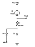
For a given circuit
attach1.PNG
determine the waveform of voltage Vout, maximum values for positive and negative half-period segments, and the average value of voltage Vout. Assume that diodes are ideal.
Given data: Frequency of sine (or cosine) wave Vin is 1kHz with magnitude 10V.

Note: This is not homework. I am practicing for exam.

When Vin>0 diode D1 is OFF, and diode D2 is ON.
In this case we have Vout=I1*R1=1V.

When Vin<0 diode D1 is ON. and diode D2 is OFF.
In this case we have Vout=I1*R1+Vin=-9V.

Maximum values for positive and negative half-period segments are V1=1V,V2=-9V.

I am having a problem finding the average output voltage.
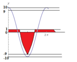
The graph is
attach2.PNG

The average output voltage is the area of a periodic function that is marked red.
Note that the first half-period segment is not a rectangle. The second part is a negative half-period segment of a cosine wave. We need to integrate that function which surface is marked red.

How to evaluate the average voltage of Vout?
 
Last edited:

Add an RC low-pass filter to the output. Select values carefully so that you do not affect circuit operation. Start with high R, low C. The idea is to make the capacitor reach an average volt level.
It is not the same as a peak detector.

- - - Updated - - -

Or if you want to do it mathematically, there is the calculus method of dividing each red area into vertical slices. Etc.
 

I want to do it mathematically, but don't know how to find integration intervals.
 

To draw the average voltage, you want to draw a horizontal line which has equal areas of red above and below it.

1) Divide the red into vertical bars. 20 bars is a reasonable amount.
2) Put a pencil mark at each bar's midpoint.
3) Measure its height above or below the zero line.
4) Add all heights.
5) Divide by 20.
6) The result is average voltage of the red portion.
 

The average voltage of a sine wave is given by the formula:
Vavg = Vpk * 2/pi (where is pi, is it π ? ) ok then 2/π
see: http: V average Formula

Because the input voltage = 10 Vpp AC the corresponding Vavg would be 6.36V
Because you chop that signal half of the time the Vavg would be ÷2 = 3.18V
Because D1 is letting only the negative half go through, then the resultant output is going to be -3.18V
Because you add 1Vdc to that signal your average voltage become -3.18V + 1V = -2.18Vavg
So this means that your answer would be given by the formula:
Vavg = 1 - Vpk/ π
This is strictly valid because your two diodes are assumed ideal
 
Hi,

If you like to do it mathematically:

First you need to know the points in time when the sine reaches the positive limit:
Let's assume diode voltage is 0.6V.
Mind calculation: about 7.2° ...please use a calculator

Your picture shows a cosine shape ... therefore i calculate with the cosine.
Usually the cosine is zero at 90° and 270°

Now from 0°... (90° - 7.2°) the value is 0.6V
Then from (90° - 7.2°) ... (270° + 7.2°) it follows the cosine
Then from (270° +7.2°) ... 360° it is 0.6V

Now you need to calculate the integral for your cosine from (90° - 7.2°) ... (270° + 7.2°)
And add the integral of 0.6V for the rest of the time.
Divide it by the period time

For sure you can calculate the same with radians instead of degree

Edit: I just recognized I missed the second diode and the voltage drop across the resistor.
I hope it helps anyway...if not, ask..

Klaus
 

Status
Not open for further replies.

Similar threads

Part and Inventory Search

Welcome to EDABoard.com

Sponsor

Back
Top