Vlad.
Full Member level 3
- Joined
- Jun 4, 2012
- Messages
- 179
- Helped
- 3
- Reputation
- 6
- Reaction score
- 4
- Trophy points
- 1,298
- Location
- Bucharest/Romania
- Activity points
- 2,568
Hi,
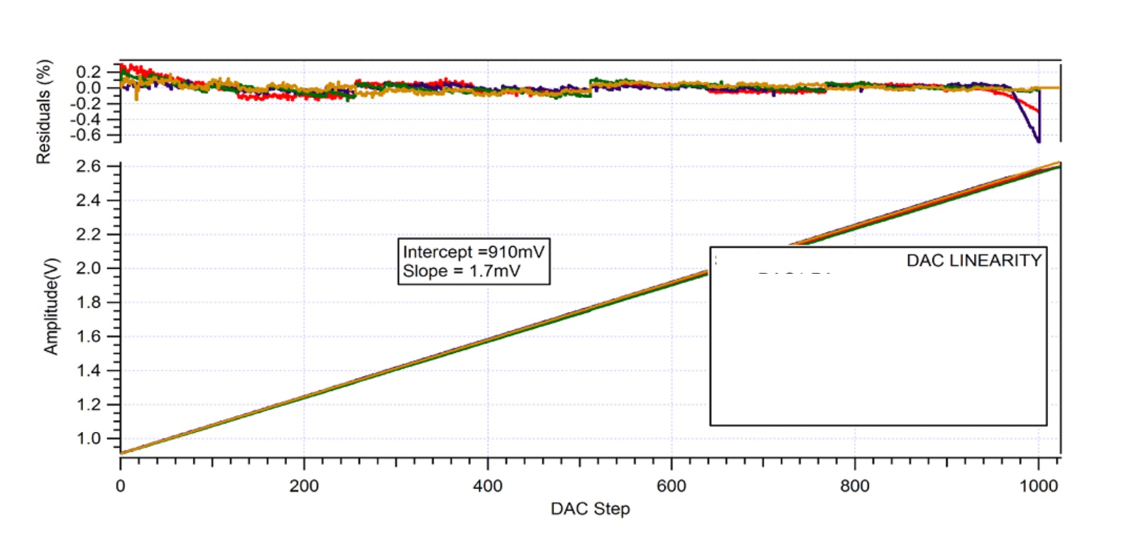
I am trying to understand what is and how can be calculated the fit residuals of an 10-bit DAC (from an custom ASIC). So, assuming we have the plots from the attached figure, which shows us the DACs linearity and also the fit residuals.
My guess is that this fit residuals are like quantisation errors, and can be estimated as the difference between the measured analog output at some registers value and the desired analog output (ideal value).
Please let me know if my way is ok on this.
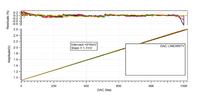
PS: The image is from this source: https://iopscience.iop.org/article/10.1088/1748-0221/8/01/C01006/pdf
Thanks,
Vlad
I am trying to understand what is and how can be calculated the fit residuals of an 10-bit DAC (from an custom ASIC). So, assuming we have the plots from the attached figure, which shows us the DACs linearity and also the fit residuals.
My guess is that this fit residuals are like quantisation errors, and can be estimated as the difference between the measured analog output at some registers value and the desired analog output (ideal value).
Please let me know if my way is ok on this.
PS: The image is from this source: https://iopscience.iop.org/article/10.1088/1748-0221/8/01/C01006/pdf
Thanks,
Vlad