Continue to Site

Welcome to EDAboard.com

Welcome to our site! EDAboard.com is an international Electronics Discussion Forum focused on EDA software, circuits, schematics, books, theory, papers, asic, pld, 8051, DSP, Network, RF, Analog Design, PCB, Service Manuals... and a whole lot more! To participate you need to register. Registration is free. Click here to register now.

RS232 spikes on receive line when disconnected

Status
Not open for further replies.

JefPatat

Newbie level 5
Joined
Jan 25, 2017
Messages
10
Helped
0
Reputation
0
Reaction score
0
Trophy points
1
Activity points
121
Hi all,

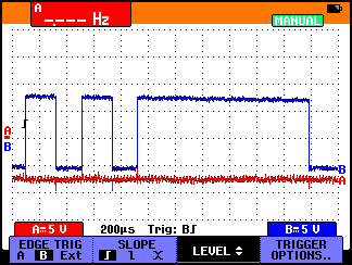
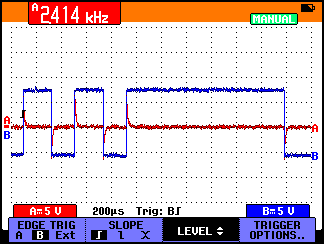
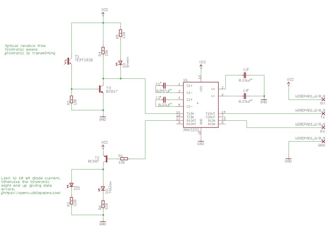
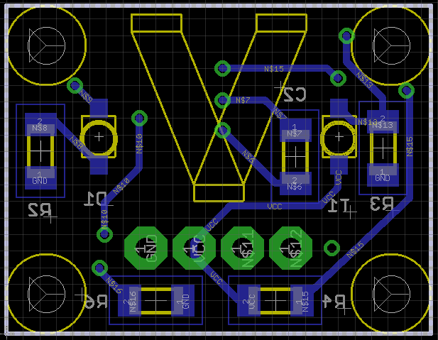
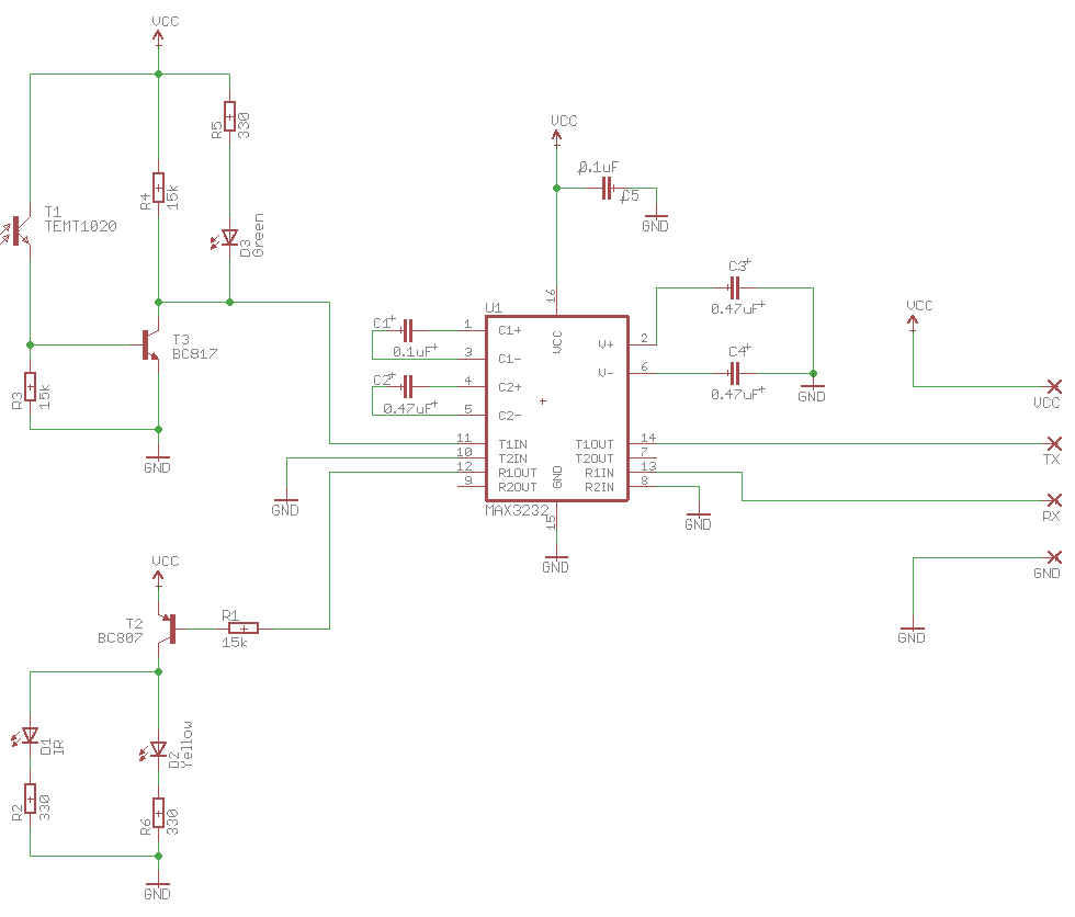
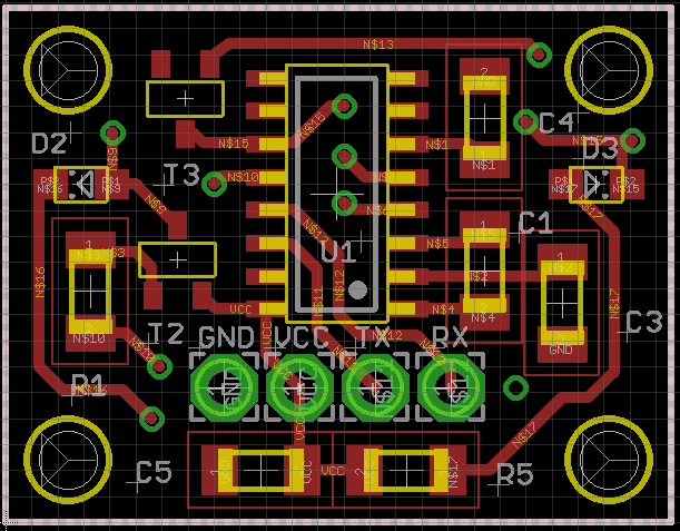
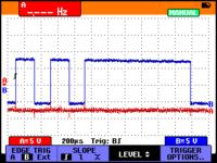
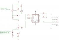
I have made the bellow schematic and attached a 12m long cable. When the cable is connected to the PC I get a nice signal but I'm observing small spikes on the RX line when the the PC is disconnected.

First question: is this because of capacitive coupling between the wires in the cable?

The circuit is receiving an infrared message every couple of seconds. The result is that the small spikes cause the yellow LED to light up. I haven't measured if the IR led emits but it doesn't look nice.

Second question: is there a remedy to what I'm observing? It's not really causing problems I think but it shouldn't be I think.

thanks in advance,
Jef


I can't see the schematic - when I 'click to enlarge' it is so blurred as to be unreadable. Can you post a higher resolution image?
I gather than the PC is at the other end of the 12m cable to where you are making your measurements, and that you are continuing to transmit regardless of any far-end connection.. In that case then the most likely cause of the spikes is the coupling between the lines in the cable.
Try a pull-down resistor on the Rx line - you can see that it is floating in your 2nd scope image compared to the first.
Susan
 
It's normal operation to receive garbage characters from a respectively long non-terminated RS232 cable when sending. This can even happen with a too large termination resistor connected to a negative voltage, e.g. 10k.
 
Hi,

If you want clean signals, then use RS422/RS485 differential signaling, with twisted pair cable, 120 Ohms characteristic impedance.

We need to see your schematic. And please give the exact type of the used cable.

The spikes ... I don't know if they cause false characters...
You could redice the spikes if you connect a series resistor at the sender...maybe 150 Ohms.
You could play with resistor values.
An RC series connection at the receiver side could also improve signal waveform.

Klaus
 

Sorry for the blurry image, I accidentally attached the thumbnail instead of the image.


The cable is a Lapp Unitronic Liycy 4 x 2.5 which I had lying around. The shield is not connected, I just use 3 wires. (gnd, rx, tx)

The measurements are taken at the rx/tx/gnd pins of the circuit, not at the PC side. (but with the PC disconnected)
I was thinking of adding a pull down, but what value, won't it be interferring with the receiver? I see that the MAX3232 has an internal pull down of 5k for example. The USB/RS232 device I'm using seems to have 4.3k.

thanks,
Jef
 

Differential will fix it but over a 12m length the problem should be too bad anyway. LIYCY cable is a particularly bad choice, it has four cores but they are spiral wound together, it would work better if the TX used two twisted wires and RX another two twisted wires to minimize coupling between them. Grounding the shield might help but it wont cure the underlying problem.

The other point I would raise is you do not show any capacitors across GND and VCC. There may be ones elsewhere in the circuit but you really need ones directly across pins 15 and 16 to prevent internal signal coupling in the MAX3232 and also to minimize noise from it's charge pumps.

Brian.
 
Brian,

sorry, forgot to mention that. My actual circuit has that capacitor. I noticed that error before but didn't update the schematic yet for version 2.
I also tried with a CAT5e cable, but that yielded the same result, so similar coupling. Actually makes sense.

The requirement is RS232 so switching to another protocol is not possible.
 

Hi,

datasheet says:
****
The transmitter inputs do not have pullup resistors.
Connect unused inputs to GND or VCC.


Generally: Don´t leave any unused (logic) inputs floating on any IC, unless otherwise stated in the datasheet.

**********************************
As already mentioned:
There is no VCC capacitor!!!! This is a "no go". Especially here with long wires to the supply and a switching application (MAX3232, bootstrap circuit, LEDs).

Use at least a 10uF bulk capacitor and a 100nF ceramics capacitor.
(use a higher value bulk capacitor at low baud rates and high LED current)

******
I recommend to use an overvoltage protection at VCC.

******

Klaus
 
Thanks Klaus. I didn't consider that information relevant to this problem. The power supply is not in the same cable at the moment, but it might be in the future. At the moment I'm using a 'cheap' wallwart SMPS.

The unused transmitter input is connected to ground in my circuit.

As I mentioned in my previous reply the capacitor is in the circuit but not on the schematic. At the moment all caps are 10uF because that is what I had lying around. I'm thinking about reducing the LED current but those components are as the schematic shows. I don't have a 100nF bypass, would that be really necessary?

I have been thinking about some protection but don't really know what to use. The PCB's size is at the limit of what I still manage to do at home and it's almost fully crowded.

I was only looking for a way to not have the second LED light up in this particular situation hence I didn't think of mentioning these other details.

kind regards,
Jef
 

Hi,

I don't have a 100nF bypass, would that be really necessary?
Yes, yes, yes....

Datasheet clearely says:
Power-Supply Decoupling
In most circumstances, a 0.1μF bypass capacitor is
adequate. In applications that are sensitive to powersupply
noise, decouple VCC to ground with a capacitor
of the same value as charge-pump capacitor C1. Connect
bypass capacitors as close to the IC as possible.
.

Please read datasheets, take the informations seriously and follow them.

Klaus
 

Although there may be a lack of decoupling capacitors, the problem discussed in the original post is unlikely related to it.

Referring to the original question, I don't exactly understand what's your problem with "spikes" seen in unconnected/unterminated RS-232 cable. As said it's just normal operation.

Standard RS-232 cables have 9 wires with common screen, the wire-to-wire capacitance isn't much lower than with said Liycy 4 x 2.5. Both will work if the Rx line is driven by usual RS-232 push-pull driver. Although not particularly reliable in the neighborhood of electrical machines, RS-232 cables with 10 or 20 m length are used in some places.
 

FvM,

thanks for the comments. I didn't mention the rest of the circuit because indeed I did think it was unrelated. It's for home usage, reading out a heater device, there won't be much noise injection. The cable is only that long because I can then sit at my desk to tinker with the software. 12m should be fine at 4800 bps is what I looked up.
It's not that I have a problem with it if it's normal operation. That's actually a bit of the idea behind my question, is this to be considered normal, I'm no expert in this. Although I admit that I would like it better if I did not see it.

Klaus,
although indeed not related to the original question I appreciate your feedback. I actually wrongly quoted you before. I meant do I need a 10uF, I only have the 100nF on the new version. I read the 'as close as possible', but to me that's very relative. I attach my new design for your reference. (Should I start a new thread for feedback on this?)

many thanks for all the input!


Hi,

I agree with FvM regarding cable, and open RxD lines.

Now to the power supply capacitors:
* Installing a bulk capacitor will not solve your problem with the spikes.
* The ceramic decoupling capacitor is mandatory.

Bulk capacitor:
I´d say it is urgent, too. Just to fulfill the datasheet requirements. A long cable (even large copper diameter) has some inductance.
It makes the current flow slow somehow: hwen your circuit needs a current pulse (to drive the LED) the current from the cable can´t react fast enough. There is some kind of delay.
This lack of power (current) supply need to be compensated by the bulk capacitor.

Do a simple test:

Connect the circuit as usual (wall wart power supply, Rx and Tx connected to the host). Then use a scope and check power supply voltage.
Now send some signal via IR transimtter LED. I assume there will be negative peaks.

Do various tests with and without bulk capacitor to see the difference.

****
If you use the LIYCY cable for transferring the power.. then expect some microHenries of inductance.
Le´t calculate with 10uH.

This forms a second order low pass filter with your 100nF capacitor.
I expect a supply voltage break down of about 1V during the first 5us then a ringing above 100kHz.

With a 10uF bulk capacitor you could reduce the break down to only 10mV...with reduced ringing voltage and about 10kHz (if visible)


Klaus
 

Ok, I will do some tests and get back with the results. Will be somewhere next week though. First need to order some correct capacitors for this test.
 

Again nothing against good bypassing, but the post #1 waveforms suggest that the RS-232 driver is basically operating well with the 12 m cable load. The direct driver supply has 0.47 µF bypass capacitors, by the way. The main problem with 100 nF 5V bypass capacitors is that you'll see considerable ripple at the charge pump frequency. This won't disturb the MA232 but can affect other circuits powered by the same supply node.
 

Status
Not open for further replies.

Part and Inventory Search

Welcome to EDABoard.com

Sponsor

Back
Top