Continue to Site

Welcome to EDAboard.com

Welcome to our site! EDAboard.com is an international Electronics Discussion Forum focused on EDA software, circuits, schematics, books, theory, papers, asic, pld, 8051, DSP, Network, RF, Analog Design, PCB, Service Manuals... and a whole lot more! To participate you need to register. Registration is free. Click here to register now.

Audio logarithmic amplifier VS audio logarithmic clipper

Status
Not open for further replies.

neazoi

Advanced Member level 6
Joined
Jan 5, 2008
Messages
4,122
Helped
13
Reputation
26
Reaction score
15
Trophy points
1,318
Location
Greece
Activity points
36,951
What is the key difference between an audio logarithmic amplifier and an audio logarithmic clipper, if both are used in communication receivers?

My guess its that, the audio logarithmic amplifier, amplifies logarithmically both high level and low level signals, within the passband of the amplifier. However I am not sure what will happen if both high level and low level signals exist simultaneously. Will the low level signals amplified more and at the same time, the high level ones amplified less? Or will the high level signals mask the low level ones?

However in an audio logarithmic clipper all signals are amplified logarithmically, but at some point the high level signals are clipped.

I may be wrong though.
 

I think that neither audio logarithmic amplifier nor audio logarithmic clipper are commonly understood technical terms.

Even more, I can't imagine a reasonable purpose of what one might associate with these terms.

A dynamic compressor might deal with logarithmic and exponential characteristics. But not applied to the audio signal rather than to the VCA gain.

Codecs with nonlinear (e.g. logarithmic) characteristic have been used in previous digital telephony systems. But they are only useful with a decoder of complementary characteristic.
 
  • Like
Reactions: neazoi

    neazoi

    Points: 2
    Helpful Answer Positive Rating
I think that neither audio logarithmic amplifier nor audio logarithmic clipper are commonly understood technical terms.

Even more, I can't imagine a reasonable purpose of what one might associate with these terms.

A dynamic compressor might deal with logarithmic and exponential characteristics. But not applied to the audio signal rather than to the VCA gain.

Codecs with nonlinear (e.g. logarithmic) characteristic have been used in previous digital telephony systems. But they are only useful with a decoder of complementary characteristic.

I see...
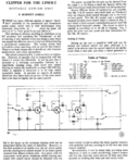
I have found this circuit, which has an input and output passive filtering (to create a BPF) and a "logarithmic clipper" as it calls this, so that the signals above a certain level are clipped.

I intend to use it in a RX circuit, where I want little or no loss of the weak signals, but attenuating the very strong signals so that they do not burn my ears when using phones.

I am not sure what this "logarithmic clipper" means. Does it mean that provides smooth clipping, instead of a simple pair of anti-parallel diodes, which provide hard clipping?

Also I guess the clipping level can be set lower because of the amplification by the transistors? If so, this will be useful to me as the audio levels in my RX, are small anyway.
 

Attachments

  • clipper.PNG
    clipper.PNG
    494.5 KB · Views: 123

My understanding of the terms is:

A logarithmic amplifier has gain control such that the output signal is a logarithmic function of the input signal.

A logarithmic clipper is a linear amplifier with an output threshold above which the level is reduced according to a logarithimc curve.

So basically one is log over it's whole input range and the other 'soft clips' it's output when above a certain level. This is an alternative to 'hard clipping' where a ceiling level is set above which the output is prevented from rising. Soft cliping is aesthetically easier on the ears than hard clipping and it still allows some increase in output, even if compressed as the input increases.

Incidentally, the back-to-back diodes (I prefer 'anti-parallel or 'heads to tails' to distinguish from ones in series) does not provide hard clipping, the attenuation they provide through a series impedance is related to their V/I characteristic which in small signal circuits is almost logarithmic. Be careful with the Liner-2 clipper configuration because it is influenced by DC on it's output point. I can't remember the input circuit of a Liner-2, only it's nickname 'Liner-Spew' because of it's ability to wipe out everything nearby with it's badly filtered PA stages!

Note: it is more usual to put the low-pass filter AFTER the clipping stage to reduce the harmonic distortion it produces.

FvM:
Even more, I can't imagine a reasonable purpose of what one might associate with these terms.
I think it's intention is to increase the average audio level before the modulator in an SSB transmitter and hence increase the average RF power transmitted. In audio applications it's use is dubious.

Brian.
 
  • Like
Reactions: neazoi

    neazoi

    Points: 2
    Helpful Answer Positive Rating
In practice no reports of audible distortion have been received.
Sounds unlikely as the circuit produces several 10 percent THD with said 20 dB clipping. It looks more like a guitar fuzz than a useful speech compressor or clipper. But surely a matter of taste.

I don't see what's the advantage over a low distortion compressor circuit as discussed in your previous thread https://www.edaboard.com/threads/363677/

The circuit will behave slightly differently if using germanium or silicon diodes, not specified in the article at all.
 
  • Like
Reactions: neazoi

    neazoi

    Points: 2
    Helpful Answer Positive Rating
Note: it is more usual to put the low-pass filter AFTER the clipping stage to reduce the harmonic distortion it produces.
Brian.

It might have been done for stability, to limit the amplifier range of frequencies it has to amplify.

Is it enough to remove c1/c3/r1 and put them after c8?
Would a coupling capacitor be needed then between the HPF and the LPF?

UPDATE.
Hey, R10 and C8 form an LPF to deal with filtering the harmonics.
How is the 500Hz-3000Hz filtering achieved? I see no HPF on the input.
 
Last edited:

There is no HPF although it is likely there is one in the Liner-2.

C1 is to prevent RF entering the circuit, it's value is too low to have any significant effect on frequency response. If I remember correctly, the Liner-2 microphone was a low impedance (200 Ohms?) dynamic type so shunting it with 470pf wouldn't change the response within hearing frequencies. Even R1/C3 have a 3dB drop at ~15KHz so they would be equally ineffective. The output filter, assuming no loading from the following stage has a 3dB drop at about 7KHz so still doesn't do much.

I fear this design is more of a "found these bits in my junk box so I used them" one than properly calculated.

Brian.
 
  • Like
Reactions: neazoi

    neazoi

    Points: 2
    Helpful Answer Positive Rating
There is no HPF although it is likely there is one in the Liner-2.

C1 is to prevent RF entering the circuit, it's value is too low to have any significant effect on frequency response. If I remember correctly, the Liner-2 microphone was a low impedance (200 Ohms?) dynamic type so shunting it with 470pf wouldn't change the response within hearing frequencies. Even R1/C3 have a 3dB drop at ~15KHz so they would be equally ineffective. The output filter, assuming no loading from the following stage has a 3dB drop at about 7KHz so still doesn't do much.

I fear this design is more of a "found these bits in my junk box so I used them" one than properly calculated.

Brian.

Do you think it would be better to connect it at the schematic at the end of this page **broken link removed** (you know I am building this one already) at the point between the first stage of the BPF and the top side of the SSB/CW switch?

I am using just the first section of the CW filter, as an SSB filter now, because it just cuts off the low and high ends. It does not have a flat response but practically SSB is heard fine.

So maybe I could connect the limiter circuit after this filter, to provide some SSB BPF as well?

- - - Updated - - -

So maybe I could connect the limiter circuit after this filter, to provide some SSB BPF as well?
Ok I did so. The circuit did not have an audible effect unfortunately. I was expecting to notice the clipping but despite the circuit gain was set high, it did not seem to clip, at least this was not audible...
 

I think you are observing the dangers of joining incompatible "building brick" circuits together and expecting the result to be the virtues of them combined. A rather poorly designed microphone compressor does not make a good receiver pre-amp!

I have doubts that what you need is a compressor at all. I appreciate the problems you hear when the audio amplitude range is so wide but to fix that at the audio stage you really need a fast responding ALC circuit, not a limiter or compressor. Likewise, a series capacitor does not make a HPF or a parallel one an LPF, if you want controled bandwidth there is no substitute for a properly designed active filter.

Brian.

Sure, I do not say the circuits I have tested do not work in general, but they just don't work satisfactorily as "blocks" on my specific circuit. Indeed that is totally different.
The three cascaded stages transistor CW filter worked like a charm and no tuning is required.
The compressor/ALC is not absolutely required, but I would like to have the ability to cut off these very loud sounds or QRM from reaching my ears. That is the only reason I consider this circuit.

I have not yet found a circuit that works satisfactorily in my RX. A way I see is to use an LDR (I tried to avoid it) in the amplifier feedback (2M2 resistor). This would be quite slow, but my experience with LDRs is that they can achieve good results.
 

Status
Not open for further replies.

Similar threads

Part and Inventory Search

Welcome to EDABoard.com

Sponsor

Back
Top