Continue to Site

Welcome to EDAboard.com

Welcome to our site! EDAboard.com is an international Electronics Discussion Forum focused on EDA software, circuits, schematics, books, theory, papers, asic, pld, 8051, DSP, Network, RF, Analog Design, PCB, Service Manuals... and a whole lot more! To participate you need to register. Registration is free. Click here to register now.

[SOLVED] Low voltage drop current sensing

Status
Not open for further replies.

kathmandu

Full Member level 5
Joined
Dec 7, 2015
Messages
298
Helped
7
Reputation
14
Reaction score
7
Trophy points
18
Activity points
3,146
Hello,

I want to use UC3845 as a control circuit for a DC-DC converter but I want to make some changes regarding the current sense circuit. My requirements are as follow:

(1) high side current sensing (using a shunt resistor)
(2) low voltage drop across that shunt resistor (low power dissipation)
(3) a cheap (no opamps and such) solution

I've designed a circuit like this:
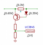
low-drop-shunt.png
Is there any way to further reduce the voltage drop across the shunt resistor? A voltage drop of 0.1V would be nice.

Do I have to play with BJTs (maybe Darlingtons) and various diode types to aquire that small (0.1V) difference? Is there any other simple solution for this?
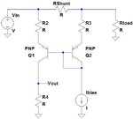
 

Obviously the circuit can't work without a diode bias current. Due to non-linear diode and transistor characteristic and temperature dependency, it's effectively useless as current sense. It could possibly work as overcurrent detector.

Dedicated high side current sense amplifiers are relative cheap and have hard-to-beat performance.

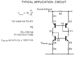
If you absolutely want to go for a discrete circuit, you should try a degenerated current mirror, the best you can do in this category. Unfortunately they suffer from rather loose transistor matching, even with available dual transistors.

Csense.jpg
 
I forgot to draw a bias resistor from Schottky cathode to ground (though it wont be necessary?)

(sorry, we've posted at the same time!)

- - - Updated - - -

You were right, I don't need a very accurate current reading. In fact, I just need to set a rough current threshold for charging a boost inductor (it's for the pulse battery charger I was talking about in another thread).

Many thanks for your suggested circuit, it actually allows to decrease the voltage drop across the shunt resistor even more (right above the noise limit).
 

you canno tuse LTC6101 or one of the cheapr diodes.com equivalents?
or what about a hall sensor?
 

Of course I could use any kind of current sensors but where's the fun? ;)

Now serious, I did mention in my first post that I'm looking for the simplest/discrete solution.
 

Hi,

I'm looking for the simplest/discrete solution.

but discrete is not simple...at least not from part count.
And I doubt that discrete is cheaper, if you take all into account. (development, fails, temperature problems, assembling cost, stock cost...)

Klaus
 
You're right, but I just needed a quick solution and, to be honest, the whole stuff is part of a small testing/practice project.

I even have some CTs available but I took advantage of this situation to do some quick researches on this subject. Being an add-on board for an existing circuit, I could further replace it with a more complex one if I'm going to need higher accuracy.

So, could you sugest another simple discrete solution (for educational purpose only)?!
 

There are discrete-appearing Hall current sensors
but these need signal conditioning. There are some
more integrated ones I've played with for DC-DC
load jigs that impose negligible resistance (just a
wire-slab through the core). However the signal
conditioning electronics are slow (op amp) and not
suitable for current mode control on a pulse by pulse
basis. More for slow monitoring and protection.

How fast and how accurate are other "design values"
in addition to simplicity, cost and board area.
 

the whole stuff is part of a small testing/practice project.

(for educational purpose only)?!

I understand what you are after. Sometimes I also build discrete circuits out of curiosity.

In that respect, you should use FvM's circuit. Yours could also work, but the forward voltage tracking between a base-emitter junction and an anode-cathode junction will not be very good.

And as suggested, for better performance a dual transistor will work best. At least you know that their individual junction temperatures will be very close.
 
There are high-side current sense chips (Maxim et al)
which look conceptually similar to FvM's topology and
I expect they are cheaper than any handful of discretes.
 

(I hope this link won't break the forum rules.. after all, the solution above has been suggested by @alexan_e (many thanks!), one of the edaboard forum administrators).
 

This type of circuits is one of the basic analog blocks that will provide you with lots of insight.

First of all, attempt to match as close as possible the Hfe for all four transistors.
Then deliberately mismatch one of them. Or heat it up with a soldering iron...see what happens to all the voltage levels.
 

By using dual BJTs, you could get a pretty good hfe matching. Moreover, the temperature should be the same for both (dual) transistors so you might actually get a pretty good accuracy.
 

I have an idea but i have not yet try configure a TL 431 a little change in
put like 5mv or 10mv its conduct anode to cathode you can configure it up side +line or down side -line
 

Status
Not open for further replies.

Similar threads

Part and Inventory Search

Welcome to EDABoard.com

Sponsor

Back
Top