Continue to Site

Welcome to EDAboard.com

Welcome to our site! EDAboard.com is an international Electronics Discussion Forum focused on EDA software, circuits, schematics, books, theory, papers, asic, pld, 8051, DSP, Network, RF, Analog Design, PCB, Service Manuals... and a whole lot more! To participate you need to register. Registration is free. Click here to register now.

output of PV should be constant

Status
Not open for further replies.

amg66

Newbie level 4
Joined
Feb 1, 2017
Messages
5
Helped
0
Reputation
0
Reaction score
0
Trophy points
1
Activity points
51
Hi, Everyone
I want to do a project for solar panle. The idea how can keep the output of PV constant by using Boost Converter for Dc Application.


Can anyone plz help me and give some advice?


Thank you.
 

Hi,

The more current you draw from the panel the lower the voltage will be.

--> If you want to keep voltage constant, then you need to adjust the current.

Read about MPPT controllers.

Klaus
 

How can adjust the current?

i did solar system connected with MPPT and from MPPT go to Boost converter to increase the output of PV.
if I do boost converter closed loop or the output from boost converter go to Voltage Regulator is it okay or not?


Thank you.
 

You need to arrange the feedback to your boost converter so it regulates the voltage across the solar panel.
It should work exactly like a shunt voltage regulator to hold the voltage constant.
When the solar voltage rises, it draws more power. When the solar voltage falls it draws less power.

Then you add a second feedback loop to that, to hold the output voltage constant.
Whichever feedback loop requires the power to be reduced wins and gains control.

- - - Updated - - -

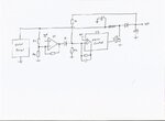
Personal message received, but I will put this up for all to see.

MPPTboost.jpeg

U2 is just the usual PWM boost controller.
The final regulated dc output voltage is set by R1 and R2 in the usual way.

U1 compares the solar panel voltage via R3 and R4 to a voltage reference.
When the solar panel voltage falls, the output of U1 rises, and D1 "fools" the PWM controller into thinking the dc output voltage has risen.
That reduces the PWM duty cycle so that the solar panel cannot be loaded down below its maximum power voltage.

Its pretty simple but works extremely well.
 
What is the output voltage that you are targeting ?
Hope you are aware that as you are using Boost topology your I/P voltage has to be always lesser than the required O/P since boost has no control over the O/P
if the input is voltage is more.
 

Hi,

MPPT and an extra regulation of PV voltage will result in problems, because MPPT already regulates according PV voltage.

Klaus
 

Hi,

MPPT and an extra regulation of PV voltage will result in problems, because MPPT already regulates according PV voltage.

Klaus

That's mean I have to do PV arrays without connecting wit MMPT
Just PV arrays then go to boost converter closed loop.
 

A MPPT controller might be still required.

What's the load powered by the boost converter?
What's the expected behavior if the requested load power is greater than the available solar power?
 

A MPPT controller might be still required.

What's the load powered by the boost converter?
What's the expected behavior if the requested load power is greater than the available solar power?

load power higher voltage for example 220 DC
i put boost converter to get higher voltage than PV
 

Another way to do solar panel converter is with one of the linear.com chips which will regulate input voltage , output voltage , input current and output current...and you choose which ones you want to regulate and in which order......eg you might regulate the input current, but have the input voltage regulator kick in if your input voltage starts going down too far......or you can roll your own one of these with multiple error ampifiers which each act to pull down the reference through their diode as and when its appropriate.
 

load power higher voltage for example 220 DC
i put boost converter to get higher voltage than PV

That is pretty much how my own system works (230v dc output) But my system is a buck boost converter, not a boost converter.

Buck boost has fewer problems for very wide range power control, because the input and output voltages can cross over.

The maximum peak power voltage is never a really sharp spike, its a wide hump or cusp, and it does not change that much over a surprisingly wide range of temperature or sky conditions. If you can hold the input voltage pretty close to the voltage shown on the solar panel rating plate, you will be getting pretty much all of the available power.

If you hook up a solar panel through a power meter to a fully adjustable load resistance, you will find that even before sunrise you will see a very few microamps and milliwatts of power, but amazingly it still peaks around the same voltage as flat out full mid day power in a clear blue sky.

Its a lot simpler than a microcontroller with perturb and observe software, but then many guys just love the software challenge, and nothing at all wrong with that approach.
Its just not really necessary.
A simple analog system will track from milliwatts to kilowatts from dawn to dusk thought the day, and track maximum power, and work perfectly well.

Many people simply refuse to believe this, but a simple power meter and adjustable load test should prove that the maximum power voltage changes by an insignificant amount over the full operating envelope.
 

Warpspeed's looks like a good way forward.....(sorry i meant "error voltage" not "reference" in my post #10 above)....and as Warpspeed seems to imply, its a good idea regulating the input voltage.....regulating the input current, then swithing over to regulating the input voltage, as i previously said, is probably not the best idea..........the linear.com chips are usually intended to regulate say the output voltage, but then let the input voltage regulation kick in if the input voltage starts going too low. But as Warpseed said, you can just regulate the Vin for great results.
 

At least in my system the 230v dc output bus stays at roughly 210v even at night (powered from the grid via a transformer and rectifier).

At dawn the solar panel voltage springs up from zero to the maximum power voltage in around 10 to 15 minutes. Only then does it start feeding current into the dc output bus. At first light, only a few milliamps, but that quickly rises as the sun comes up.

With solar sufficient to sustain any load, power drawn from the grid falls completely to zero throughout the day.

At dusk the process reverses with the grid taking a larger share of any load. Then suddenly at dusk the solar voltage begins to rapidly collase to zero within a few minutes.

I have no battery at this stage, but this system provides ALL my daytime power for about ten hours during the day during summer, which is around 75% to 80% of my total power consumption. I cannot do any better than that with more solar panels, because I can already support the total daytime load, and there is nothing I can get from the system at night.

Pretty happy with it. Its very simple, and because it all runs at a high dc voltage all the currents around the whole system are low and efficiency is very high.
 

Warpspeed, that sounds fantastic, ..and with no battery. I never thought of doing it that way…ie, having a high voltage DC bus, and not a solar inverter. That is, you make the solar system the master and let the mains come in as like a secondary back up at night.
The only thought I have is the bridge rectifier…that needs to be pretty chunky? I remember working in a shower company once, and it shocked me that electric showers take 10kW’s and are supplied from household single phase mains….so that’s 43 Amps.
 

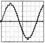
I do have a sine wave inverter, its not PWM but a multistep inverter that combines the output of three square wave inverters.
This is a picture I found on the internet, but the unfiltered output my own inverter looks exactly like this:

Stepped Wave.png

It requires +/- 230v dc input bus and produces 240v rms sine wave output.
The three separate square wave inverters just use IGBTs in half bridge.

High power PWM can be problematic, especially with really nasty reactive loads. The stepped waveform inverter being completely bi directional, and easily handles a lot of out of phase current thrown back at it. Its very simple and robust.
A lot less EMI too.
Pretty happy with it, I would never now go back to PWM unless the required power output was very low.

I am very fortunate to have three phase power at home. I use three large toroidal transformers that step down the voltage and a bridge rectifier, large common mode choke and two electrolytics.
Its a very stiff low ripple supply of around +/- 210 volts.
 

Status
Not open for further replies.

Part and Inventory Search

Welcome to EDABoard.com

Sponsor

Back
Top