Continue to Site

Welcome to EDAboard.com

Welcome to our site! EDAboard.com is an international Electronics Discussion Forum focused on EDA software, circuits, schematics, books, theory, papers, asic, pld, 8051, DSP, Network, RF, Analog Design, PCB, Service Manuals... and a whole lot more! To participate you need to register. Registration is free. Click here to register now.

Li-on battery charger

Status
Not open for further replies.

JordanElektronika

Junior Member level 2
Joined
Jun 25, 2015
Messages
22
Helped
0
Reputation
0
Reaction score
0
Trophy points
1
Activity points
311
Good day! I am making a small circuit to power a LOAD through a Battery and power supply. I am making the circuit as simple as possible otherwise I can do it with a PIC microcontroller.

I have: Li-On battery at 3.7V to be charged with 1 to 2A. The load will drain 1 to 2A also. Through the battery I power a LOAD. Through the POWER SOURCE I power the BATTERY.

These few points bother me:
1. Will this circuit really work despite that it looks like it should?

2. Given the 1Ohm resistor will this have any effect at all given that when we make the PCB board the traces will have some resistance or the cables if we solder it manually and will that resistance be 1Ohm also? If the resistance of the Traces is 1Ohm the current should drop in half?

3. If I connect a phone to the batter of the circuit will the phone get charged or discharged?

4. I am using a Zener to keep the voltage at 4.3V. Is that good if we do not know the type of battery that will be used for the circuit and the type of LOAD connected (might be a cell phone) is 4.3V enough? I think I should remove the Zener because the battery will get overcharged or should I leave it to get charged to 4.3V?

5. What is the maximum to which I should consider the battery being discharged - maybe 3V?

6. I have left a diode if the battery drains a too high current the diode will burn and it also prevents the current from the battery to go in the wrong direction?

battery-charger.jpg
 

Hi,

I see the folowing problems:
* Li-Ion is a sensible device. If you don´t treat it as you should it may explode.
* The zener isn´t suitable to regulate the voltage as exact as the Li-Ion needs
* The zener has too low power dissipation
* the zener may draw current when charger is not ON

Conclusion: Don´t o it this way.
There is a good reason why Li-Ion chargers are a bit complex and need tightely tolerated comonents.

Don´t hurt yourself.

Klaus
 
These few points bother me:
1. Will this circuit really work despite that it looks like it should?

Yes, it looks like it should. Select the power dissipation for the zener suitably.

2. Given the 1Ohm resistor will this have any effect at all given that when we make the PCB board the traces will have some resistance or the cables if we solder it manually and will that resistance be 1Ohm also? If the resistance of the Traces is 1Ohm the current should drop in half?

I presume the resistance of the PCB traces will be far less than 1 Ohm; unless you make a lousy solder joint, that too will be considerably less than 1 Ohm.

3. If I connect a phone to the batter of the circuit will the phone get charged or discharged?

That depends on the voltage and current needed for the phone charging. Please check the phone charger instructions and manual.

4. I am using a Zener to keep the voltage at 4.3V. Is that good if we do not know the type of battery that will be used for the circuit and the type of LOAD connected (might be a cell phone) is 4.3V enough? I think I should remove the Zener because the battery will get overcharged or should I leave it to get charged to 4.3V?

Zeners are not so precise in regulating the voltage and the current and the heating determines the final voltage drop. You need to experiment.

5. What is the maximum to which I should consider the battery being discharged - maybe 3V?

Your present circuit does not have a provision to prevent over discharge of the battery.

6. I have left a diode if the battery drains a too high current the diode will burn and it also prevents the current from the battery to go in the wrong direction?

I do not see the diode in the diagram.
 
Ok so the zener will be a problem. The diode is "D3" right after the resistor. I will try another approach. At how much voltage should I charge the Li-ON battery?
 

Hi,

At how much voltage should I charge the Li-ON battery?
There ar many thread here discussing the charging of Li-Ion batteries.
Usually every Li-Ion manufacturer (at least the good ones) give detailed informaion about charging parameters.
Additionally there are plenty of high quality discussions about Li-Ion charging in the internet.

I´d say: there is no simple and safe way.

Aagin: It´s not unlikely that you hurt yourself (or others) or burn your house.

The problem with Li-Ion is that you don´t have time to react when something gets wrong. It starts an avalanche process that may immediately lead to a serious explosion.
Other battery types are not that critical.

Klaus
 
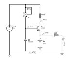
These are my 2 other ideas but the simulator gives wrong values for some reason. Otherwise by calculation

1. Transistor schematic
We have a bipolar transistor used a current generator.
Uemitter = Uzener - 0.6V
Iemitter = Ibase * alpha = Uemitter / Battery resistance = Icollector = (5V - U[ce]sat + Ucollector) / Rcollector

The current through the zener is:
5V - Uzener = 0.3V / 30Ohm
 

These are the ideas.

The thyristor should stop when the battery reaches the voltage of the zener.

battery-charger1.jpgbattery-charger2.jpg
 

Hi,

Tesla trust Panasonic, me too! Some of the answers to your questions can be found in the pdfs.

When will EDABOARD run a hotly-pursued and evidently very popular competition for "Curious 1950's Li-Ion Charger Circuit Notions Based on Ramming the Current in Full Whack"? ;)
 

Attachments

  • panasonic_li-ion_charging_information.pdf
    380.3 KB · Views: 45
  • panasonic_precautions_and_safety_notes_for_li-ion_batteries.pdf
    408.6 KB · Views: 59
Dont get me wrong. Using ready circuits is something I should do but I am trying to do it by myself. See what I know and what I dont. My best idea is use a microcontroller and a MOS Fet transistor like 2NF6782 or the Bipolar 2N3054 and just turn them on and off at 20kHz with the microcontroller. I can put 1 resistor of 3 Ohms in the collector or drain so I limit the current. Thanks for the PDfs though! They will be useful!

Here is the schematic with a microcontroller.
1. I have a question: shouldnt the voltage over the resistor and battery be 3.7V or whatever comes from the source minus the voltage on the source resistor? There is a small loss over the transistor also. So by theory I should power both the load and the battery and the current from the battery should also power the load? When there is no charging current the battery will power the load. When there is charging current, the battery will get charged and at 3.7V will have a high resistance so the load will get most of the current?

2. I am trying to make a device that will power a load and charge a battery. When the source is unplugged the battery will keep on charging the load otherwise both will be charged?

3. I put the 3Ohm resistor in case the battery is very discharged like (2Volts) despite that it shouldnt fall under 3.
 

Hi,

...there's no schematic.

Guessing here: The battery charging voltage needs to be (required V to charge battery + V dropped across resistor + Vce/Vds (+ anything else in the path that will drop voltage)). Provisionally, I don't think so, pardon me if I'm mistaken but I think you want it to work that way, but physics/nature may disappoint you... no idea what batteries do when full, couldn't say if they develop a previously non-existant high resistance once charged...Not sure if you wouldn't need some sort of comparing circuit (e.g. a comparator or whatever) to switch the battery out of the circuit once fully charged.

I'm no expert at all..., some battery/other power source designs just use a diode to stop the battery flowing back into the power source, and the higher voltage usually is what - to express it badly - the load chooses; there is also the simple choice of a DC barrel jack with three pins that selects the external power source automatically by separating the two NC contacts used for V+.

I thought Li-Ion mustn't be discharged to less than 3V?

Here's another pdf about battery chargers.
 

Attachments

  • Battery Charging snva557 TI.pdf
    146.6 KB · Views: 42
A small point to remember:

In the worst case, the battery is down and the load is on. The load takes 1-2A and the battery is also a similar amount. Hence the power supply must be rated around 4-5A (just to keep a small headroom). The supply voltage must not drop too low under high current.
 
Status
Not open for further replies.

Similar threads

Part and Inventory Search

Welcome to EDABoard.com

Sponsor

Back
Top