Continue to Site

Welcome to EDAboard.com

Welcome to our site! EDAboard.com is an international Electronics Discussion Forum focused on EDA software, circuits, schematics, books, theory, papers, asic, pld, 8051, DSP, Network, RF, Analog Design, PCB, Service Manuals... and a whole lot more! To participate you need to register. Registration is free. Click here to register now.

Help in Type of MOSFET driver

Status
Not open for further replies.

PVM137

Newbie level 4
Joined
Jan 22, 2017
Messages
5
Helped
0
Reputation
0
Reaction score
0
Trophy points
1
Activity points
43
Hi everyone.
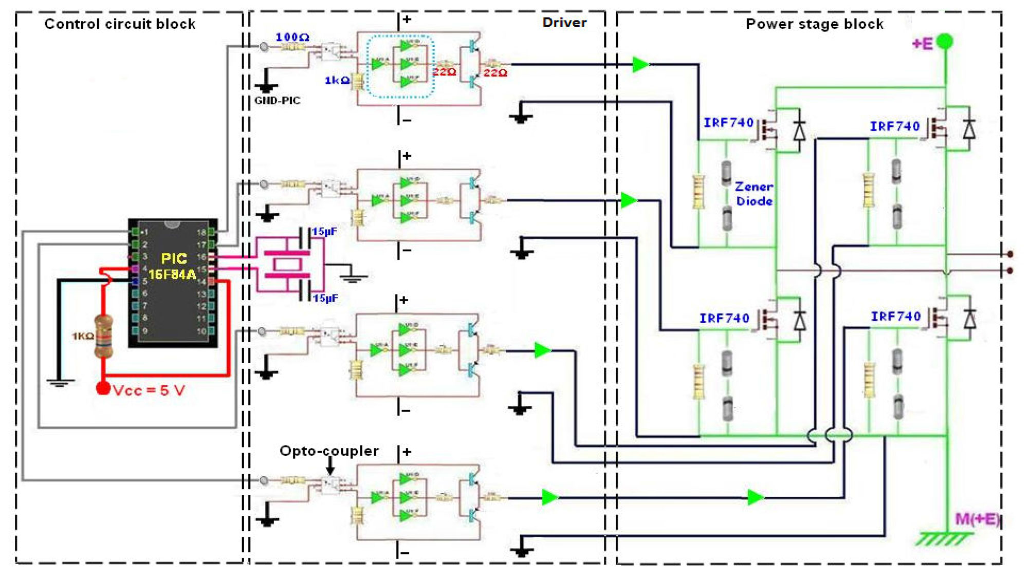
In this schematic what type of driver used?
Does 4 driver with specific components should used? or 2 driver IC can handle?
And what capacitor value should used?

This system can generate high voltage&frequency along with a HV transformer


The "drivers" are evidently those little clusters of inverters
and discrete BJTs. I think this scheme is doomed, the optos
are slow and dissimilar (& not well controlled) delay / edge
rate, there are inverters placed in the gate legs of the
power FETs trying to make phase inversion but standard
inverters are too weak and too low-voltage.

If you really need isolation as shown, might look into
newer isolated gate driver chips. Or, a better isolation
in the digital domain followed by a full bridge driver IC
that does the proper phasing. Rather than making the
uC do an idiot's job creating phases that counteract
all of the hardware timing nonidealities, yet doing no
useful regulation at all. Is the point simply to say you
did a "digital power converter"? Because that's about
the only reason for a uC here.
 
  • Like
Reactions: PVM137

    PVM137

    Points: 2
    Helpful Answer Positive Rating
It's rather a design sketch than an actual schematic and shouldn't be taken too serious. It completely hides the gate driver supply, it shows 4 pairs of "+" and "-", without clarifying that the two high side driver supplies must be individually isolated from the low side, also it misses the ground reference to MOSFET source.

Annotating crystal capacitors with 15 µF instead of 15 pF casts another light on document quality.
 
  • Like
Reactions: PVM137

    PVM137

    Points: 2
    Helpful Answer Positive Rating
The "drivers" are evidently those little clusters of inverters
and discrete BJTs. I think this scheme is doomed, the optos
are slow and dissimilar (& not well controlled) delay / edge
rate, there are inverters placed in the gate legs of the
power FETs trying to make phase inversion but standard
inverters are too weak and too low-voltage.

If you really need isolation as shown, might look into
newer isolated gate driver chips. Or, a better isolation
in the digital domain followed by a full bridge driver IC
that does the proper phasing. Rather than making the
uC do an idiot's job creating phases that counteract
all of the hardware timing nonidealities, yet doing no
useful regulation at all. Is the point simply to say you
did a "digital power converter"? Because that's about
the only reason for a uC here.

In this type of supply, the PIC controller generate a square signal of adjustable high frequency. at the same time, a rectified and adjustable voltage (0-310 V), that feeds the primary of a step-up ferrite transformer, is transformed in a high frequency signal by the MOSFETs (IRF740) controlled by the square
signal, thereby obtaining an adjustable high voltage output.

َAnyway, my problem is in type of driver section and connections to inverter(4 IRF740).
??
 

The selection of driver depends on the frequency of operation and output current capability of the driver IC. You can use two single leg driver with suitable current capability. Look into infineon's IR2110 driver IC which has the capability to drive both high side and low side mosfet. There are similar IC from texas UCC27714. All use similar technology.

You question is can a single driver IC driver two mosfet in parallel ? Answer is simple. If the IC can supply gate charge to the MOSFET for suitable turn on, then It can drive two mosfet simultaneously. But there is another problem with a full bridge circuit. You have to turn on a one HV side and one LV side mosfet. Considering all this you should choose IC. All type of IC are available, single output HV/LV side driver (IR2118/IR2117) or dual output ICs.
 
  • Like
Reactions: PVM137

    PVM137

    Points: 2
    Helpful Answer Positive Rating
Status
Not open for further replies.

Similar threads

Part and Inventory Search

Welcome to EDABoard.com

Sponsor

Back
Top