Continue to Site

Welcome to EDAboard.com

Welcome to our site! EDAboard.com is an international Electronics Discussion Forum focused on EDA software, circuits, schematics, books, theory, papers, asic, pld, 8051, DSP, Network, RF, Analog Design, PCB, Service Manuals... and a whole lot more! To participate you need to register. Registration is free. Click here to register now.

Feedback Phase of flyback

Status
Not open for further replies.

ElecDesigner

Member level 5
Joined
Jul 22, 2014
Messages
94
Helped
4
Reputation
8
Reaction score
5
Trophy points
1,288
Activity points
2,190
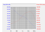
I've got a LT isolated, closed loop, flyback demo board straight out of the box and am looking at the gain/phase plots etc.

My question is about the phase. Do I interpret the phase margin here as about 55deg or 235deg. Looking at other examples I think it must be the latter because of the low frequency phase. Seams weird but the phase "bump" is very big.
Any reassurance greatly appreciated!
CapturePhaseGain.PNG
 

The phase curve doesn't seem to make sense at first sight. How did you capture it?

Which LT switcher IC/Eval board is it?
 

Did you use the board in the default configuration as shipped?

Can you show how you connected AP300?
 

The board was straight out of the box except I added 20R in place of the 0R (R15).

Signal injector put across the 20R and probes at each of the 20R (both referenced to the secondary ground). Standard configuration for this equipment as I understand it. The gain plot looks very believable so I think I must have got it right....
 

Sounds reasonable. I also agree that the magnitude plot looks plausible. But the phase doesn't, I believe.
 
Status
Not open for further replies.

Part and Inventory Search

Welcome to EDABoard.com

Sponsor

Back
Top