Continue to Site

Welcome to EDAboard.com

Welcome to our site! EDAboard.com is an international Electronics Discussion Forum focused on EDA software, circuits, schematics, books, theory, papers, asic, pld, 8051, DSP, Network, RF, Analog Design, PCB, Service Manuals... and a whole lot more! To participate you need to register. Registration is free. Click here to register now.

Measure Voltage on Batteries in Series

Status
Not open for further replies.

nima_1981

Member level 3
Joined
Apr 22, 2010
Messages
61
Helped
0
Reputation
0
Reaction score
0
Trophy points
1,286
Location
Ocean Mind
Activity points
1,877
Hi ,
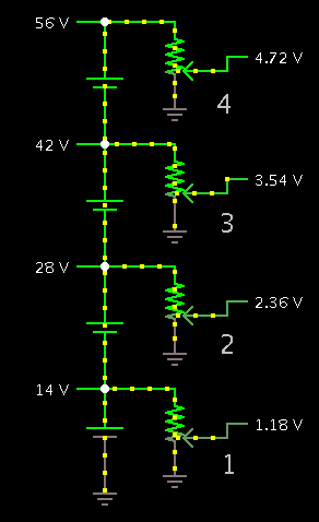
Could you please help me for read voltage battery in series same as this block diagram but Adc of microcontroller. how i can divide voltage of each cell ?
Thanks in advance

photo_2017-01-25_04-07-09.jpg
 

Here is a method which is easy to work with. The goal is to reduce each reading below 5V. Derive each battery's voltage by subtracting one reading from another.

If you don't have 4 adc inputs then you must create a 1-of-4 selector.

6058737200_1485321529.png


I made each battery 14V because they can rise that high during charging. (In fact I saw my 6V golf cart batteries reach 7.5V if I charged them too long on a sunny day. That's like 15V in a 12V battery.)

Why not make a simple resistor network? It seems as though it ought to be possible. However that gets very involved. Tough to figure out for some reason.
 
Hi,

I recommend equal two_resistor voltage divider for each node.

Btw: this has been discussed before in this forum.

Klaus
 

The circuit in post #2 will not allow you to read each battery voltage separately, if that's what you want.

One way to do that is to use a difference amplifier across each battery, and sequentially select the output of each amp with a multiplexer.

The simulation of an example diff amp circuit is shown below.
The LT1991 has well-matched on-chip resistors to give high common-mode rejection.
The resistor are connected for a gain of 0.25 giving an output of 3.5V for a 14V battery voltage.
That also gives sufficient common-mode range with a 15V supply to handle >60v common-mode voltage.

Capture.PNG
 
Edit to my post #4 above.
A standard op amp could be used to form the differential amplifiers using standard 1% resistors, but that would cause an input voltage measurement error of up to 1% of the common-mode voltage, or 420mV when measuring the top battery voltage with a 42V common-mode voltage.
 
All the really decent data loggers use a fully floating precision voltmeter which can be directly connected across each battery via relay contacts.

Resistor networks can introduce measurement errors, and if the batteries are very small, the resistors will set up a continuous discharge which will be uneven between batteries. It would certainly work, but it is far from the perfect solution.
 

.......................
Resistor networks can introduce measurement errors, and if the batteries are very small, the resistors will set up a continuous discharge which will be uneven between batteries. It would certainly work, but it is far from the perfect solution.
An IC difference amp, as I proposed in post #4, has the resistors matched very closely so the error from that should be acceptably small.
And most 12V batteries will not change voltage significantly with a draw of a tenth of a milliamp of current or so.
So, although that solution is not perfect, I think it's closer than "far". :wink:
 

Thanks crutschow ,
i can not find LT1991 in our region ? could you please redesign that with ad620 or another popular opamp such as tl084.
 

i can not find LT1991 in our region ? could you please redesign that with ad620 or another popular opamp such as tl084.
Since you didn't post your physical "region" I didn't know what you can or cannot: purchase. :-?

I can design it with a standard op amp but you will need 0.1% resistors to minimize the common-mode error I mentioned.
Either that, or I will need to add pots and you will experimentally have to null out the error.
Which is best for you?

What power supply voltages do you have available?
 
sorry for bad wring ! I'm beginner in English . no i can not purchase that in my country its unavailable here.
about power supply i have +5 V , -5 and Gnd
and i can purchase 0.1 % resistor .
Thanks for your kindness .
 

Here's a difference amplifier circuit using a TL084.
The first stage has a low gain of 0.075 so that its common-mode voltage of 5V (with a 5V supply) is not exceeded.
The first stage resistors must be 1% to minimize common-mode error voltage (56mV worst-case).
This is followed by an amp with a gain of 3, for an overall gain of 0.225, giving an output voltage of about 3V for a battery voltage of 14V.
V2 represents three batteries in series.

You put one each of these circuits across the battery terminals (In2 positive) you want to measure.


Capture.PNG
 
Last edited:
Status
Not open for further replies.

Part and Inventory Search

Welcome to EDABoard.com

Sponsor

Back
Top