Continue to Site

Welcome to EDAboard.com

Welcome to our site! EDAboard.com is an international Electronics Discussion Forum focused on EDA software, circuits, schematics, books, theory, papers, asic, pld, 8051, DSP, Network, RF, Analog Design, PCB, Service Manuals... and a whole lot more! To participate you need to register. Registration is free. Click here to register now.

charging and discharging of the capacitor using two pulses of 180 phase difference

Status
Not open for further replies.

prateek3790

Full Member level 2
Joined
Feb 8, 2016
Messages
131
Helped
1
Reputation
2
Reaction score
1
Trophy points
18
Activity points
1,190
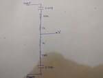
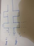
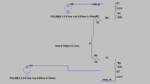
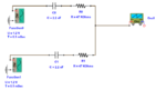
hi i have one rc network and i am applying two square pulses of opposite phase(both are from 0 to 1.2v so when one is 0 the other one 1.2v their freq is 10KHz) to them then i was expecting that the potential at the middle of the network @V will be 0.6v. can someone tell how the charging and discharging is happening.
 

Attachments

  • IMG_20170123_230853.jpg
    IMG_20170123_230853.jpg
    464.2 KB · Views: 59
  • IMG_20170123_231009.jpg
    IMG_20170123_231009.jpg
    474.3 KB · Views: 50

Hi,

The DC voltage at the middle is undefined, because both capacitors are high impedance for DC.

But with precise input signals it won´t change. Theoretical no AC signal.

****
Short circuit both capacitors and the middle voltage will be DC 0.6V

Klaus
 

A complete circuit with voltage sources and ground connection would make a clear question.

Taking the proper ground connection for granted, yes the center node will stay at constant 0.6 V. This can be concluded by simple symmetry considerations without calculating the actual current and voltage waveforms. But they can be easily derived, I guess you already know that the step response of a RC circuit is an exponential function.

- - - Updated - - -

KlausST is right that the center node is DC-wise floating. It would show a voltage of 0.6 V though if the input is zero for t<=0 and the pulse generator switched on for t>0.
 

but on doing simulation i am seeing that it is nowhere near 0.6v and drops to -ve voltages as well. I was hoping it will wander around 0.6v
 

Attachments

  • pulse_v1.PNG
    pulse_v1.PNG
    17.6 KB · Views: 59
  • pulse_v2.PNG
    pulse_v2.PNG
    17 KB · Views: 53
  • sche.PNG
    sche.PNG
    14.7 KB · Views: 57
  • voltage_plots.PNG
    voltage_plots.PNG
    76.2 KB · Views: 57

Don't know what you did wrong. I see either 0 V output or 0.6V output when setting UIC option (skip initial transient solution), as expectable.
 

Don't know what you did wrong. I see either 0 V output or 0.6V output when setting UIC option (skip initial transient solution), as expectable.

can you tell any other simulator, i am using ltspice, or any online circuit simulator

- - - Updated - - -

i am getting 0-600mv when only one of the source is being used, i tried using online simulator, they are giving 0 voltage, when both the sources are active
 

Attachments

  • both sources results.png
    both sources results.png
    42 KB · Views: 101
  • both sources sch.png
    both sources sch.png
    21.4 KB · Views: 55

Hi,

As said before: the DC voltage is not defined for your configuration. It may be anywhere. -100V, -17.4V, +63.2V or any other value.

Some simulators run a DC analysis...they may fail because of this "undefined" situation.
Other simulators may assume the capacitors are completely discharged (0V) at start up.
Maybe some capacitor models have "leakage resistors" defined... then the DC output voltage is defined.

Klaus
 

A SPICE based simulator should give correct results with UIC option activated which enforces the conditions I mentioned in post #3 (all voltages 0 for t <=0, analysis starts at t>0). Ltspice does.

rc.jpg

Nevertheless you may doubt about the purpose of this circuit.
 
A SPICE based simulator should give correct results with UIC option activated which enforces the conditions I mentioned in post #3 (all voltages 0 for t <=0, analysis starts at t>0). Ltspice does.

View attachment 135626

Nevertheless you may doubt about the purpose of this circuit.

Thanks a lot. now this is what i measured.
Just one doubt though if i am not enforcing the condition then why they are effecting, i mean by default when the simulation is started why it'll take the condition before t<0.i am applying my pulses at t=0 and also capacitor do not have any initial voltage.(i am assuming this is how it should have been am i right? )
 

Without UIC option, the initial generator voltage of 1.2 V is applied and capacitors are precharged. The floating output node, although its voltage is undefined as mentioned by KlausST, is pulled in Ltspice to 0 V by a default minimal node conductance. This behavior depends however on various analysis options and might be different with default settings of different SPICE analysators. In so far you shouldn't rely on it.

Needless to say that you don't have it in a real circuit.

so the capacitor are charged @ t<0.
but in real case it's start charging only after t>0.
 

The capacitors are charged during initial transient solution. It acts like an infinite time interval which can't occur in a real circuit. Review a SPICE tutorial for details.
 
can you tell any other simulator, i am using ltspice, or any online circuit simulator

- - - Updated - - -

i am getting 0-600mv when only one of the source is being used, i tried using online simulator, they are giving 0 voltage, when both the sources are active

You do not differentially drive the circuit .Reverse one of the source polarization.
 

Hi,

i am getting 0-600mv when only one of the source is being used, i tried using online simulator, they are giving 0 voltage, when both the sources are active
What else do you expect?

Klaus
 

just one doubt why the potential remains constant , i mean take the top capacitor it will charge when one of the source is active and when the other is active it will discharge so that potential will start building up on the other side of the cap. why this action are not seen in the results.
during charging it's upper plate will move towards 1.2v and lower plate will go towards 0.6v. during discharging the bottom plate will try to go to 0.6v and upper plate will go towards 0. but how the bottom plate remains at constant 0.6v
can someone explain the results in terms of charging and discharging of capacitors.

- - - Updated - - -

You do not differentially drive the circuit .Reverse one of the source polarization.

actually it's part of respiration sensors design
 

but how the bottom plate remains at constant 0.6v
May be you are talking about a different circuit? The "bottom plate" doesn't stay at 0.6V, only the center node "V" does. You can watch in your simulation.

As previously mentioned, simple symmetry considerations show that the center node stays at a constant voltage when both voltage sources are swinging exactly out of phase.

sorry for the wrong assumption.
but can you tell how the capacitor voltage will be changing on both of it's plate for the capacitors.
 

"in terms of charging and discharging of capacitors":
Capacitor voltage (difference between plate potentials) will change according to

ΔV = 1/C*∫Idt

As the same current flows through both capacitors (no output load at node V), both capacitor voltages change simultaneously by the same amount.
 

Status
Not open for further replies.

Part and Inventory Search

Welcome to EDABoard.com

Sponsor

Back
Top