Continue to Site

Welcome to EDAboard.com

Welcome to our site! EDAboard.com is an international Electronics Discussion Forum focused on EDA software, circuits, schematics, books, theory, papers, asic, pld, 8051, DSP, Network, RF, Analog Design, PCB, Service Manuals... and a whole lot more! To participate you need to register. Registration is free. Click here to register now.

VIH and VOH: How can I deal with them?

Status
Not open for further replies.

jasensio1

Newbie level 6
Joined
Aug 11, 2016
Messages
12
Helped
0
Reputation
0
Reaction score
0
Trophy points
1
Activity points
115
Hello guys.

I've got a driver running at 3V and a receiver running at 3.3V.
According to datasheets, these are threshold values:

Driver: VOH 2.4V min (4 mA)
Receiver: VIH 2.5V max. Input max current 0.5 uA

First thought is that they are not compatible but, are variations between min, typical and max values for this parameters something that can be under control?

If I keep the output current much lower than 4 mA, can I expect in any case voltages close to 3V at driver output?

Many thanks
 

Hi,

well done to look for the specifications.
It is very likely that connecting both will work, but as you recognized, it is not guaranteed.

If I keep the output current much lower than 4 mA, can I expect in any case voltages close to 3V at driver output?
Often in the datasheet you will find a VOH to IOH current chart. This will tell you.

What about simply using a pullup resistor?

Or a level converter. Almost any 74HC, 74LV, 74LVC, 74AHC ..device should work.

Klaus
 
Hi Klaus.

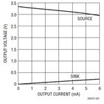
This is the graph showing driver VOH, for Vcc = 3.3V.

VOH.jpg

So here is the main question...VOH is a consequence of output current only, because output impedance I guess?
 
Last edited:

That is correct, both Voh and Vol will converge towards the middle as its loading increases; as you correctly determined, by the device's output impedance.

In a different thread, I discussed how to interface 3.3 volt logic with 5 volt logic:

https://www.edaboard.com/threads/362920/

The key is to use a HCT series device. The "T" means the input levels are TTL compatible, and as discussed in the thread, they make interfacing compatible.
 
Hi,

The key is to use a HCT series device.
I agree that "T" devices are good for 3V0 or 3V3 to 5V0 interfacing.
But most (all?) "T" type logic ICs need 5V power supply (4.5...5.5V), but here the higher supply voltage is 3.3V only.

Klaus
 

Hello.

The point is that I am facing 2 main problems:

1) My system is battery powered, so I need low power stuff, 2-3 uA quiescent current as maximum in stand by mode.
2) The line I need to adapt is a serial bus running up to 115200 bps, so I can't think about a transistor based solution which is fast enough to keep good signal shape and low baud rate error
 

Thanks Klaus, for spotting that detail...

Anyways, the essence of my comments are still valid. Make sure, by reading the datasheets, that the logic level pairs Voh/Vih and Vol/Vil between the driver and the driven device are compatible.
Light loading also does help significantly.

EDIT: something that I also investigated to validate the assumption, I powered up the 3.3 volt device with a variable power supply.
I reduced its voltage to the minimum operating voltage of 2.6 V. Its Voh dropped accordingly, but the circuit continued to function correctly.
 

Hi,

look at the datasheets for:
NC7SZxx (3V0 supply)
NC7Sxx (3V0 supply)

My recommendation:74LVC1Gxx, 3V3 supplied, but V_IH= 2.0V

Klaus
 

Status
Not open for further replies.

Similar threads

Part and Inventory Search

Welcome to EDABoard.com

Sponsor

Back
Top