KhaledOsmani
Full Member level 6
Hello,
I want to make a circuit that does the following:
1) When there is complete darkness (regardless of the sensitivity) I want to actuate relay R1 (12VDC coil)
2) If still there is darkness, (R1 is ON), and there is a motion (detected by a PIR), I want to actuate relay R2 (12VDC coil).
3) When R2 is actuated, and hence NO becomes NC, I want to light a small bulb for a certain delay dictated by the PIR sensor it self.
The purpose of such circuit, is, when you are sleeping, and urgently woke up to do something, there would be a helping light. Or if a visitor entered, and does not know where the bulb switches are, the light will help him for few seconds so he can discover the room.
No digital programming/microcontroller is intended to be used.
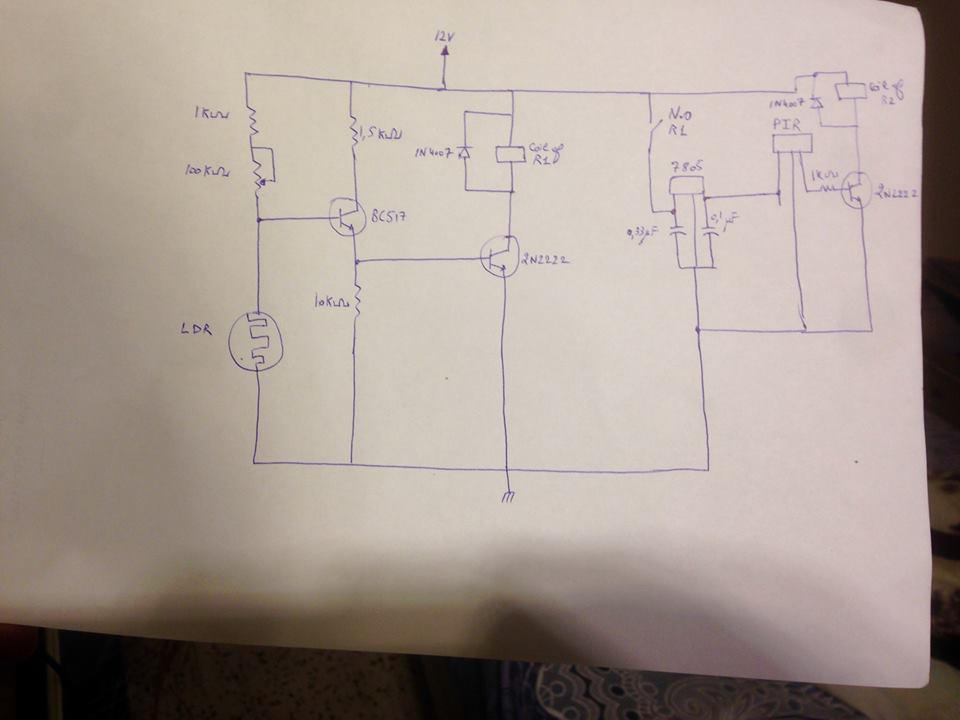
Here is the circuit:

All components are clear, except for the PIR, it must have a 5VDC as input, delivered by the 7805 regulator.
When soldered the circuit no problem existed, so I manipulated the sensitivity of the LDR, using the 100K pot, and switched lights off, to a complete darkness. R1 got actuated, and since I was near the PIR sensor, R2 was also actuated. You can set the sensitivity level, and output duration using two screws on the sensor it self.
The weird thing, when lights are off, and motion is detected, instead of having the bulb (LED bulb operated under 220VAC) normally glow for duration regulated from within the sensor, it starts flickering repeatedly, as ON/OFF, and so on.
Before asking what is the problem and how the circuit must be justified, from the PIR datasheet, it says that when connected to a power source, and detected motion the user must wait for 1 or more minutes in order for the sensor to stabilize. If this is the only problem, how can I minimize the "startup" time for the sensor or neglect it (please don't tell me I have to remove caps and re-solder other ones).
Thanks in advance
- - - Updated - - -
Added: the flickering light is caused by repetitive on/off of the relay at ms between each turn.
When no bulb is connected this does not happen. i.e the relay doesn't excessively turn on and off
I want to make a circuit that does the following:
1) When there is complete darkness (regardless of the sensitivity) I want to actuate relay R1 (12VDC coil)
2) If still there is darkness, (R1 is ON), and there is a motion (detected by a PIR), I want to actuate relay R2 (12VDC coil).
3) When R2 is actuated, and hence NO becomes NC, I want to light a small bulb for a certain delay dictated by the PIR sensor it self.
The purpose of such circuit, is, when you are sleeping, and urgently woke up to do something, there would be a helping light. Or if a visitor entered, and does not know where the bulb switches are, the light will help him for few seconds so he can discover the room.
No digital programming/microcontroller is intended to be used.
Here is the circuit:
All components are clear, except for the PIR, it must have a 5VDC as input, delivered by the 7805 regulator.
When soldered the circuit no problem existed, so I manipulated the sensitivity of the LDR, using the 100K pot, and switched lights off, to a complete darkness. R1 got actuated, and since I was near the PIR sensor, R2 was also actuated. You can set the sensitivity level, and output duration using two screws on the sensor it self.
The weird thing, when lights are off, and motion is detected, instead of having the bulb (LED bulb operated under 220VAC) normally glow for duration regulated from within the sensor, it starts flickering repeatedly, as ON/OFF, and so on.
Before asking what is the problem and how the circuit must be justified, from the PIR datasheet, it says that when connected to a power source, and detected motion the user must wait for 1 or more minutes in order for the sensor to stabilize. If this is the only problem, how can I minimize the "startup" time for the sensor or neglect it (please don't tell me I have to remove caps and re-solder other ones).
Thanks in advance
- - - Updated - - -
Added: the flickering light is caused by repetitive on/off of the relay at ms between each turn.
When no bulb is connected this does not happen. i.e the relay doesn't excessively turn on and off