Continue to Site

Welcome to EDAboard.com

Welcome to our site! EDAboard.com is an international Electronics Discussion Forum focused on EDA software, circuits, schematics, books, theory, papers, asic, pld, 8051, DSP, Network, RF, Analog Design, PCB, Service Manuals... and a whole lot more! To participate you need to register. Registration is free. Click here to register now.

SG3525 / KA3525 Oscillator test (plasma cutting board)

Status
Not open for further replies.

VanUnamed

Newbie level 3
Joined
Jan 14, 2017
Messages
4
Helped
0
Reputation
0
Reaction score
0
Trophy points
1
Activity points
35
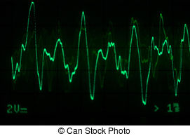
Hello, I have a KA3525A Chip that controls a plasma cutter board. The plasma has been checked for all obvious faults (defect is it turns on gives air but no "sparks") nothing turned out to be faulty. I have checked pin 11 and 14 (the two outputs) in circuit with an oscilloscope and instead of getting a square wave like it is supposed to on the dataheet I get something like a sawtooth wave. I have removed said chip from the circuit but I have no idea exactly how to test it separately from the circuit, I was thinking to apply about 12V on VCC ( I have 11V on VCC when in circuit) and then check with the scope again, but I don't think it can be that easy.
I have also checked tiny transistors around the IC, resistors, and capacitors as well, but only the electrolytic ones. the chip takes its VCC supply from a board down below (the one where the AC gets in) and the connector has 24V as printed on the board)

Thanks for any reply.
 

You can check the chip according to the test circuit in the data sheet, but I would think to just swap the chip and see. The outputs must be a square wave unless something is damaged in the chip, or it is being loaded down by whatever is connected to it.
It will help if you can post a picture of the scope display.
 

thank you for your kind reply e-design. the waveform I didn't take a picture of it unfortunately, it is something along those lines

2712943000_1484418293.jpg


When the machine trigger is pressed it gets ten times faster, but always same shape.
What could possibly load it?
 

The chip normally gets damaged by something further down the line, like a Power MOSFET or driver being damaged. So make sure your power devices are ok and not damaged.
 

hello, is that possible that the chip developed an internal fault and that's it? I have checked everything down the line until the isolation transformer that then goes to the mosfets. all mosfets are goods, all parts from pin 11 and 14 are good. any thoughts? thanks!!!
 

Ok, sorry for last post. I have been checking more, I have 2x mosfets per channel, one channel has irfz24n the other one 9z24n (irf as well) the 9z24n are faulty. Once I change this and try i will mark this thread as solved :)
 

Status
Not open for further replies.

Part and Inventory Search

Welcome to EDABoard.com

Sponsor

Back
Top