Continue to Site

Welcome to EDAboard.com

Welcome to our site! EDAboard.com is an international Electronics Discussion Forum focused on EDA software, circuits, schematics, books, theory, papers, asic, pld, 8051, DSP, Network, RF, Analog Design, PCB, Service Manuals... and a whole lot more! To participate you need to register. Registration is free. Click here to register now.

[SOLVED] Pulse transformer Problem in high duty ratios

Status
Not open for further replies.

badea

Member level 1
Joined
Mar 15, 2016
Messages
37
Helped
6
Reputation
12
Reaction score
6
Trophy points
8
Activity points
260
Dear Friends:
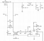
while trying to isolate a control signals for H-bridge by means of pulse transformers (SIRIO 108020) i got good signals in small duty cycle (lower than 10% @ 30Khz)
but when i raise a duty cycle, output of pulse transformer start to slop e down as shown in pictures
Any idea to solve this problem?


regards
15970418_1220228718025649_623932425_n.jpg15978947_1220228681358986_1873095820_n.jpg
 

It seems that even the initial amplitude is less
than the narrow-duty case.

I'd start with looking at the primary side waveform
voltage, and current. It may be that the xfmr is
a load that the driver is not capable of handling
at a high duty factor. Wide pulse lets current
ramp higher and could be overheating the driver
output.

But also look at current; if the current is not
returning to zero by the end of each period
then you could be saturating the core (and
this will worsen driver load / overheating). It
might be possible that a narrow duty, low
volt-seconds pulse can be "quenched" in the
period, but a higher volt-seconds pulse is not
and each pulse incrementally "winds up" the
core.

You might need a beefier transformer in that
case but also a means of scrubbing off any core
energy.

Driving the primary with a low-Z CMOS output
(like a MOSFET driver) might let current circulate
(pump from VDD, but when high side drive is off
and low side turns on, current simply continues to
circulate from VSS). You may -want- a lossy drive
scheme.
 
  • Like
Reactions: badea

    badea

    Points: 2
    Helpful Answer Positive Rating
You need a pulse transformer with much higher inductance.

That particular transformer is probably fine for firing an SCR or Triac with very short gate drive pulses.
For longer pulse durations it simply is not going to work.
 
  • Like
Reactions: badea

    badea

    Points: 2
    Helpful Answer Positive Rating
Hi,

It seems you prevent it from going negative, so the core may saturate.

* show use the complete circuit
* why do you want it to be flat?

Klaus
 
  • Like
Reactions: badea

    badea

    Points: 2
    Helpful Answer Positive Rating
The transformer is specified with a V*t integral of 250 µVs, so it should be able the transmit similar pulses without saturation.

But the circuit matters
- it must allow reset of transformer flux over a cycle, or in other words zero voltage average across the winding
- it must drive the primary with sufficient low impedance to provide the magnetizing current

Show the circuit
 
  • Like
Reactions: badea

    badea

    Points: 2
    Helpful Answer Positive Rating
It looks underpowered or overloaded.
 

Your circuit does not allow the transformer to reset.
Please see the circuit below on what is required:
transformer drive.PNG

The actual component values are critical and require to be matched to the actual devices employed, the switching frequency, the driver's output voltage, and maximum and minimum duty cycle.

I calculated the values with the help of a very valuable app note from Texas Instruments, which unfortunately I cannot locate right now

The bottom image is my implementation on an actual circuit.
 

Attachments

  • transformer drive.PNG
    transformer drive.PNG
    12.6 KB · Views: 251
Last edited:

Hi,

I agree.

Diode D2 only allowes small negative voltage (0.7V). This means slow decay.

If your secondary side can withstand negative voltage then simply add a zener in series to D2.
This allowes a limited (zener) negative voltage. Maybe use a 12V zener.

****
Negative voltage means negative voltage across the transformer.
Usually the transformer top connection is positive and the transformer bottom connection is GND wsen switch is ON.
But when switch is released (OFF) it generate a positive 12V level with respect to the top connection. This means the bjt collector temporarily sees 12V + 12V = 24V

Klaus
 

You need a pulse transformer with much higher inductance.

That particular transformer is probably fine for firing an SCR or Triac with very short gate drive pulses.
For longer pulse durations it simply is not going to work.

you are right, i used this pulse transformer to firing scrs and it works successfully.
maybe this model not able to produce a long duty on its output coils
 

The transformer definitely needs to be capacitively coupled to your driver, which should swing hard rail to rail.

That creates another problem on the secondary at extremes of duty cycle.
There will need to be another coupling capacitor and diode, exactly as Schmidt Trigger has shown in his circuit.
All this will work, but beware of very fast slewing of the duty cycle.

The coupling capacitors need to be made fairly large to work, but they also need time to establish correct dc levels at the mosfet gate.
Very fast slewing of the duty cycle can cause great upset at the gate, and while that may not be too serious in some circuits, it can be pretty lethal if it causes even momentary cross conduction.

Transformers are excellent for fixed 50% duty cycle gate drive, but are problematic at extremes of duty cycle.

I myself prefer opto isolators for this type of application, you can still use your pulse transformers (driven at a constant 50% duty cycle) to generate four fully isolated dc power supplies to power the individual opto isolated gate drivers.
Many different ways to go about all this, but pulse transformers have problems you can well do without.
 

When i removed a free whell diode D2 i got a good response on all duties but a negative voltage appears on output stage
final.jpg
i will solve this problem by a diode

thanks all for valuable replies
 
Last edited:

Hi,

This was quite expectable.
But I can't remember that someone recommended to remove D2.
Removing D2 may kill your bjt.

Klaus
 
  • Like
Reactions: badea

    badea

    Points: 2
    Helpful Answer Positive Rating
Status
Not open for further replies.

Similar threads

Part and Inventory Search

Welcome to EDABoard.com

Sponsor

Back
Top