battery.13v
Newbie level 4
Hello everyone !!!
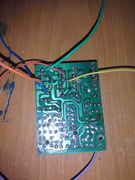
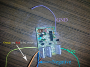
i have this 2 RC car toys in the junk ... so i have the idea to modify them into one car that has much power and speed .... So i reassemble them into one frame and i got this one :
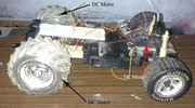
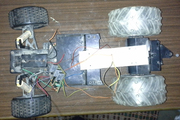
This new Toy contain 2 DC motors in the Rear and One Steering Dc Motors in the front ...
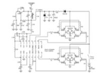
the old circuits contain just 2 H-bridge for 2 Dc motors, when i test it one H-Bridge is Burned out cause i connect it to 2 Rear Dc Motors,
So i figured out that i have to add a new H-Bridge to my second rear Dc Motor ...
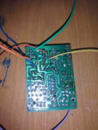
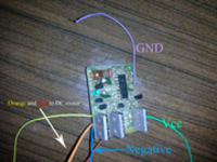
The demodulator is a chinese clone of the RX-2 Chip ...
When i tested it's output i found that it output pulses (when i trigger forward it generate a positive pulse ...
and when i release the forward trigger, it generate a negative pulse ) and with this pulses it make the DC Motors Runs ....
So i searched in the Internet and i figured out that it could be a latching circuit after this pulses ...
However when i retrace the Circuit i did not found any LAtching Circuit ...
So this is my problem and i want someone to tell me how this thing "Chinese RX-2 Chip" control the DC motors with Pulses ?????
You will Found in the attachement the circuit schematic of the H-Bridge
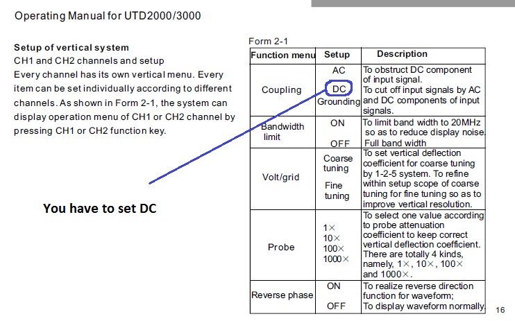
Here is a video about the result of the oscilloscope in the output of the left and right ouptut pin signal
https://sendvid.com/hguz65wg
So i want to know how this thing make a dc motor turn on ??
How could i make another H-Bridge that trigger on with this kind of pulse for my Third DC Motor ??
Thx ??
i have this 2 RC car toys in the junk ... so i have the idea to modify them into one car that has much power and speed .... So i reassemble them into one frame and i got this one :
This new Toy contain 2 DC motors in the Rear and One Steering Dc Motors in the front ...
the old circuits contain just 2 H-bridge for 2 Dc motors, when i test it one H-Bridge is Burned out cause i connect it to 2 Rear Dc Motors,
So i figured out that i have to add a new H-Bridge to my second rear Dc Motor ...
The demodulator is a chinese clone of the RX-2 Chip ...
When i tested it's output i found that it output pulses (when i trigger forward it generate a positive pulse ...
and when i release the forward trigger, it generate a negative pulse ) and with this pulses it make the DC Motors Runs ....
So i searched in the Internet and i figured out that it could be a latching circuit after this pulses ...
However when i retrace the Circuit i did not found any LAtching Circuit ...
So this is my problem and i want someone to tell me how this thing "Chinese RX-2 Chip" control the DC motors with Pulses ?????
You will Found in the attachement the circuit schematic of the H-Bridge

Here is a video about the result of the oscilloscope in the output of the left and right ouptut pin signal
https://sendvid.com/hguz65wg
So i want to know how this thing make a dc motor turn on ??
How could i make another H-Bridge that trigger on with this kind of pulse for my Third DC Motor ??
Thx ??
Attachments
Last edited by a moderator:
")