Continue to Site

Welcome to EDAboard.com

Welcome to our site! EDAboard.com is an international Electronics Discussion Forum focused on EDA software, circuits, schematics, books, theory, papers, asic, pld, 8051, DSP, Network, RF, Analog Design, PCB, Service Manuals... and a whole lot more! To participate you need to register. Registration is free. Click here to register now.

Seeking advice regarding structure of a DC-DC/PWM reg. for personal vaporizer.

Status
Not open for further replies.

David_

Advanced Member level 2
Joined
Dec 6, 2013
Messages
573
Helped
8
Reputation
16
Reaction score
8
Trophy points
1,308
Location
Sweden
Activity points
12,217
Hello.

I am designing my own driver circuit for a personal vaporizer, it's a device containing batteries, a LCD/OLED and a couple of buttons,the devices function is to supply power to a atomizer to vaporize a liquid containing nicotine.

I want to keep the device as small as possible but the max output power will be 100W, possibly 80W.
and I have to decide whether to use a DC-DC Buck-Boost solution or a Boost converter plus PWM.

The battery voltage will come from a 3,7V Li-ion battery so between 4,2v and maybe 3,2V or whatever the specific low voltage limit of the battery is at.


There will be a MCU to control everything, it will have to measure the resistance of the heating coils attached to the atomizer and be able to adjust the output power ether by adjusting a Buck-Boost converter output voltage or by controlling the output of a Boost converter for higher than battery voltages and then use PWM for lower voltages.

It isn't relevant jet(don't think it is anyway) but the device should be able to regulate the atomization process by setting a specific output wattage or by using "temperature regulation" in which mode the room temperature resistance of the heating coils is saved and then by determining the change of the resistance calculate what temperature the heating coils are at by also knowing what kind of metal there made out of. And then limit the output power to maintain a specific temperature.

To begin with I thought I would ask for advice on how to design a boost converter to boost the voltage from a 3,7V Li-Ion battery and to use it's full capacity, and I think I want more than one MOSFET in order to spread out the heat and to make the sources of heat larger in order to keep the PCB cooler.

But I have looked around for suitable control ICs but I am somewhat lost regarding what kind I should use, I have been pondering if I should use a DAC and a 3 resistor feedback divider to be able to adjust the voltage.

Does anyone know of any boost/buck-boost converter IC which uses external MOSFETs to suggest?

The output power should be able to go to 100W but with a controller with external MOSFETs the output current is dependant on the MOSFETs right.

I'm not really sure about what the problem is I am having and which makes me write here now.

Regards
 

Nebulizers are essentially same thing and are widely used in atomic absorption spectrophotometers; but the 100W power appears very high. The battery may not last long (what is the AH capacity you will be using) but that is beside the point.

Nicotine water phase diagram (solubility curve) is rather interesting. See https://www.everyscience.com/Chemistry/Physical/Mixtures/g.1271.php for some basic idea. What is the concentration you will be using?
 
  • Like
Reactions: David_

    David_

    Points: 2
    Helpful Answer Positive Rating
Nebulizer hah, I never heard of those but from a quick look at google I can imagine the similarities.
I am switching batteries every day at least once, and the liquid I am using is bought as a 100mg/ml dissolved into propylene glycol and then I mix it with vegetable glycerin(and more nicotine free propylene glycol) into a liquid that contains 6mg/ml nicotine and consists of 30% propylene glycol and 70% vegetable glycerin. And then flavour concentrates is added which is dissolved into propylene glycol most often anyway, and in the end I have 6 or 6,5mg/ml nicotine in the liquid, but that is changing over time, I started at 18mg/ml which is an enormous amount if used in a RDA which I am using now(There pictures coming) but I have keept dropping the nicotine level.
I don't remember how many procent nicotine that is but a small number of %.

I'll might as well show you kind of what I am designing.

MOD.jpg
As you can see standing next to the device in the picture it uses 18650 batteries(this particular device uses 2 such batteries in series), the battery in the picture is one of the weaker of the batteries I have, if I recall correctly the green battery in the picture has a peak discharge current of 25A. Peak discharge current is specified in a lot of different way's but all of them seems to define a situation which covers the duration of time that this device is active for i full inhale.

The black thing on top is the atomizer or RDA(Rebuildable Dripping Atomizer) in this case and it is attached through a 510 connector and is easily switched for another, there are hundreds to choose from, some have tanks containing anything from 1ml to 6ml of liquid.

The black covering is pulled of and reveals the heating coils with cotton wicks trough them:
Coils.jpg

And when you hit the button on the side power is applied to the atomizer, in this case 60W:
Active Coils.jpg

This particular Atomizer is one with which you drip the liquid into the atomizer through the top peace, which you then inhale from.

But the circuit that this thread is concerning is meant for my own device sort of like the one in the pictures only this will be designed and then 3D printed and mounted with a special connector which has a hole through it.
Inside the device there will be 1 18650 battery or more than one smaller batteries together with a soft plastic bottle filled with nicotine liquid, from the bottle there goes a tube to the atomizer connector which has a hole and the atomizer also has a hole through its connecting part.
So if I squeeze the bottle through a hole in the device liquid is pushed into the tube through the connector and into the atomizer, you see there are many advantages when using a RDA such as in the picture(more flavour for one thing) but the downside is that you need to be carrying a bottle of liquid besides the device and then drip it into the atomizer and refill quite often, this project will solve that problem for me:)

I will look through that link.
 

To extract 80W from a 3.7V battery, you get best efficiency if you draw 25-30 A continually from it. This suggests interleaved converters, or, an H-bridge with transformer.
Parasitic resistance cannot be more than 1/10 ohm total.
Expect to need 8 to 12 AWG wire.
 
  • Like
Reactions: David_

    David_

    Points: 2
    Helpful Answer Positive Rating
Let us assume that you apply 80-100W to a heating coil made of kanthal wire of a few turns. If you leave it on for more than a sec, it will get easily above 350-400C (perhaps more). You spray the nicotine dissolved in solvents on the hot coil. The solvent evaporates rapidly and you a left with a nebula (dust of nicotine; but nicotine is a liquid) that you want to inhale.

Both PG and Glycerin do not evaporate well but gets charred; that produces an acrid smell. You can dip a matchstick into glycerin and then put the stick in a flame. The smell is difficult to describe in words but some people do like it (the smelly staff is called acrolein).

What is the final temp of the filament you want? Please state some range.
 

First I thought that I needed some more elaborate DC-DC converter but let me show you an example of the PCB taken from a device that is capable of more than what I want to design for, I've encircled the battery, B+ & B-(Though the B+ silk screen isn't visible) and also OUT+ & OUT- which is connected to the 510 connector, or in other word to the atomizer, or in again other words to the heating coils.
coilside.jpg
lcdside.jpg
The red circle on the LCD side of the PCB is the same node as OUT-, and the LCD hides two very large resistors which I think are the current sense resistor(s).

My first plan was to use this board and build a new box for it so up until now I have spent lots of time creating an accurate 3D model of it to be used in Fusion 360 when I design the box around it, so I haven't spent any time figuring out the circuit, but apart from being able to find out that the LQFP-32 package is a STM8 MCU the other ICs are unknown and I can't find a match online for anything written on them. But I think it i a pretty solid bet to say that those square ICs, U1, U8, U2, U3, U6 & U11 are MOSFETs...

The black button is the activation button while the other two are menu or setting buttons, i don't have any DMM here right now but I will go get one later and start tracing out the connections so that maybe we can figure out what the topology of this thing is, if it isn't obvious to someone, I first thought that the MOSFETs was probably paralleled in order to spread the heat and lower the RDSON but I don't feel confident that that is the case without having measured it out.
But during searching online for MCU based boost converter I have seen people driving MOSFETs directly from a MCU I/O pin which doesn't seems like a good idea at all, MOSFETs need much higher currents to turn on/off fast don't they?

Oh right, this PCB is from a box with 2 18650 batteries in series so the switcher on the PCB is only of the buck variety.

But let me just say that the device on the pictures have max current of 25A.

c_mitra, I'll answer you shortly.

- - - Updated - - -

Ether I use temperature regulation in which case the device don't apply power when the coils temperature is estimated to be above a set limit which I usually have set to somewhere around 220degC, but most often I use a mode they call power mode, in which you set a wattage value and when you press the button that amount of power is released until you let go of the button or hit the 10sec cutoff which I never ever even come close to.

And while using the power mode I have no idea what kind of temperature it is, I have been planing to measure it with a thermocouple to see how accurate the device can estimate temperature and to see what temperature the coil get to while I vape it in the power mode.
But I am fairly confident that the temperature does not get above 300DegC, I pretty sure I never hit 400degC anyway, but then it might be relevant to add that the cotton that is put through the coils is never ever allowed to dry up and they are keep saturated with liquid at all times, if they get dry you get what is known as a dry hit which I have never had the unfortunate to inhale but it is supposedly really really nasty.

PG and VG seems to be very suitable for this purpose, I can smoke all day long and in the end there is no charred remains to speak of, the wire get coated with a black surface after a few days if I don't switch coils and the cotton might get a little darker,the part of the cotton that is covered by the coil.

- - - Updated - - -

I have been reading about what kinds of metals are safe to use and it seems as there are widely available metals sold for the purpose of vaping that isn't at all determined to be safe, I only use Kanthal and SS316 which is two metals that seems as having been proven to be safe to use, of course if you would put them under a high enough temperature then it might get dangerous but those temperatures isn't approached while vaping as it is normally done.

It's better than tobacco anyway.
 

Curiously you didn't yet mention a heater resistance. What is it? My first approach would be simple pwm heater control instead of buck or boost converter.
 
  • Like
Reactions: David_

    David_

    Points: 2
    Helpful Answer Positive Rating
That's a good point, my ordinary kanthal dual-coil setup has in total 0,18Ω. But over all I never use a total resistance higher than 0,5Ω.

One aspect of these devices which commercially is important is that they should be able to be adjusted over a large range, when I use the "wattage" mode(I described it as power mode) I use 60W but some of the recipes that I enjoy needs to be vaped with temperature regulation and the atomizer I currently have capable of that needs to be used as low as 20W while limiting the max temperature to some value.

It don't have that much experience with temperature regulation because the device I own, the one in the pictures have some software bug or something that prevents me from using temperature regulation in all cases except if I use one particular Clearomizer(evolution of the atomizer) which needs lower wattage.

But I don't know, the hole boost idea comes from the fact that I don't want 2 18650 in series but rather 1 single battery or some other combination of smaller batteries in order to come out in the end with a smaller device(as I need room for a bottle of liquid inside of the device as well) but I'm not at all sure that there isn't another better way to do this.
I just got interested in designing a boost converter but if you have a better suggestion I am all ears.

- - - Updated - - -

I haven't decided yet but people whom I meet is interested in my design but for now it is non-commercial.
I don't even want to begin thinking about what would be required of me in order to be allowed to sell a thing like this, it is after all potentially dangerous.

- - - Updated - - -

And I want to do this for fun and to get a device that has the features I want, and I don't want to be thinking about what is economically viable, of course that is always a consideration but as it's a hobby project I can choose solutions which wouldn't be possible if one wanted to sell it.
 

I frequently see a person walking across a road then they disappear into a cloud of vapour. Cars on the road cannot see them and they are in danger of being hit.
I also frequently see a car disappear into a cloud of black diesel smoke. Cars on the road also cannot see them and they are in danger of being hit.
 

... my ordinary kanthal dual-coil setup has in total 0,18Ω. But over all I never use a total resistance higher than 0,5Ω....

If you have two coils, then they can be more messy to control- they are in series or in parallel? Or, they are being regulated independently- of course I have not understood much.

In the constant power mode, the geometry of the coils play a role because the temp is stable only when the energy input is balanced by the energy loss by conduction and radiation.
 

There are different atomizers, some are single coil, some have possibilities for dual or even quad-coils, I know there are some that can use two coils in series but every atomizer I have used have been connecting them in parallel.

But I winding the two coils at one and the same time(I take a peace of wire and fold it at the center point and then I wind these two wires at the same time. Only to then cut of the peace of wire where then fold is made so that I can twist the now 2 separate coils apart and that results in 2 pretty much identical coils which is then mounted with great care to ensure that there are mounted and fastened equally).

I have been thinking and I am not entirely sure about what option I should go for and I haven't even decided if I will design the device in the same fashion as commercial devices is done, that is there are made to work in a wide range of power settings, or if I will limit this somewhat to what I know I use in order to simplify the design.

The problem with the last option is that I might change my preferred usage in time so I will probably go for a more elaborate design.
What I really are looking forward to is getting into designing the temperature regulation algorithm which sounds as a very interesting programming endeavor.

I had first thought to try and find an alternative to 18650 battery in the hope of finding a more space saving solution but I think I will stick with 1 18650 battery(since then I can continue to use my external charger and do not have to be as aware of the battery safety stuff, though short circuit protection is needed as well as a battery charge monitoring system to display an estimation of how much charge is left and to alert when the battery is empty).
I do need to read more about battery safety in any case.

I thought a good idea is to take the time to figure out how the chip I have is working, if anyone wants to know it is the chip from a **broken link removed**.

There website provided a surprising amount of information about how there design works, it really isn't much information but I was expecting no real info at all so that nice.

Here is the relevant information which may be relevant to show you how such a device might work in very broad terms, very broad.

The KOOPOR Plus features Dual Driver System and HFDMR (High-Frequency Dynamic Monitoring Resistance) Technology, is one of the most accurate temperature-control mod ever made! It provides 200w maximum power, and takes dual 18650 batteries that can allow most vapors to enjoy vaping all day! Aside from superb performance, the KOOPOR Plus is the definition of fresh and aesthetic. It’s guaranteed to make heads turn!

Material: Stainless Steel and Zinc Alloy
Output Power: 6w-200w
Output Voltage: 0.35v-8.00v
Resistance Range: 0.08Ω—3.00Ω (Temp Mode)
0.10Ω—3.00Ω (Watt Mode)
Standby Current: < 300µA
Maximum Current: it should be less than 50A when the atomizer resistance is 0.1 ohm.

Temperature Control
Temperature protection between 200°F and 600°F(or 100°C-315°C)
  • Under temp mode, KOOPOR Plus can recognize your coils made of Ni200 alloy, Ti and SS.
  • Be careful to only attach new atomizers that have cooled to room temperature to the mod.
  • When using a new atomizer or reconnect your existing atomizer under temp mode, the KOOPOR Plus will prompt “NEW COIL UP SAME DOWN” to allow you to confirm the change.

Dual Driver System
KOOPOR Plus has integrated our own Dual Driver System that works to buck and boost the voltage to improve the accuracy and speed of regulating, and enhance the consistency and taste of every puff.

**broken link removed**

High-Frequency Dynamic Monitoring
Resistance Technology

HFDMR, is a high-frequency resistance sensing technology, which can detect atomizer resistance once every 250 microseconds,
with a precision of approximately 4000 times per second, thus regulating the temperature of heating coil more effectively.

200w Super Power
It provides variable wattage from 6w to the maximum 200w to give you more freedom to control your vapor!

Large OLED Display
It presents all key pieces of information, including output wattage, output voltage, atomizer resistance and remaining battery life, etc.

I hope that gives a more detailed description for what kind of device I am after, though the Koopoer Plus does sound as being more elaborate than what I will be able to do, but we shall see.

But that high frequency resistance measurement function seems crucial and I would love to be able to detect even lower values than 0,08Ω.
The battery I will use for this device is a 18650 BASEN BS186Q 3100mAh 3,7V which has a peak discharge current of 40A.

Well first of all the Koopor Plus PCB design is a lot more professional than what I am able to do, but I am also capable as this is a hobby project to spend more both in cost and PCB real-estate to maybe enhance some functionality in circuits such as the resistance measurements, I think so at least. One important aspect will be the PCB design and the usage of small SMD packages, I am also considering capacitance sense technology to implement the buttons but that may very well be dropped later on.

If I want a as smooth and accurate a regulation as possible, what topology would be recommended?
 

If I want a as smooth and accurate a regulation as possible, what topology would be recommended?

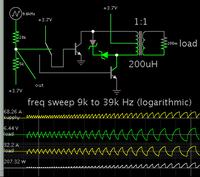
By switching at a lower frequency to a transformer you increase output.
A higher frequency reduces output.

This topology is the center-tap primary. Only one switching component is in the current path at a time, and it draws smoother waveforms than a single boost converter. Duty cycle is always 50 percent. (With a boost converter you may find it impossible to operate at a high enough duty cycle, so that you get 100W to a 0.2 ohm load.)


Theoretically you could get more than 100W average. Parasitic resistance must be minimized so it is as little as possible.

The lefthand control section is a contrivance to make the simulator create a smooth frequency sweep, which is applied to a SPDT switch.
 
  • Like
Reactions: David_

    David_

    Points: 2
    Helpful Answer Positive Rating
...**broken link removed** ...

Very nice curvaceous curve but I could not understand what is TC control and what is Vape Effect. There are no number or scale marks or tics on either axis.

It is certainly designed to be irreproducible but the salesman can sell a refrigerator to an Eskimo!!

Do you mean that we are actually seeing the switching pulses as oscillations?
 
  • Like
Reactions: David_

    David_

    Points: 2
    Helpful Answer Positive Rating
Brad, thank you for answering my question. I think that I might have asked a incomplete question though, or it depends.If I was to prioritize the size of such a transformer, how small would you guess that I could get away with?
I wonder because I would be prepared to make room for at transformer as long as it isn't too large, if I could make it compact enough it would actually be a really cool design, but if it is too large then I have to go for a MOSFET only design.

mitra, that graph is I suspect actual nonsense and all it does is illustrate the sensation of vaping with some mods(devices). Some of them use poorly implemented PWM regulation which one really does feel while vaping, that graph is a quite good illustration of that since you can feel how the device is increasing, decreasing, increasing, decreasing the power applied such as the curvature in the graph, I am actually not 100% certain that such bad implementations is due to PWM regulation but the better mods presents a vaping sensation illustrated by the smooth line.

If the transformer can be made small enough then Brads suggestion is something I would like to look closer at.

If that don't work out I believe that I will go in the direction of the others whom have designed to best personal vaporizers and follow the Buck-Boost converter design, much because I'd like to learn how to control such a circuit with a MCU but also because I know that it can perform what I want it to.

Now about that transformer, is a transformer that should be able to transfer 100W going to have to be a certain size or is there anything i can do to minimize the size, with air-gaps or some unconventional heat sinking or something?

I have for a while been thinking that a peltier element could be used to cool a single device in order to get away with stuff you wouldn't ordinarily, or rather imagine that maybe it could.
 

This all seems over-complex (and unrealistic) to me.

The 100W has to come from the batteries you state,
and that means from a single 3.7V lithium cell you
need 30A (or more depending on inefficiency). That
is outside the range of almost any small cells.

The e-cig vaporizers make do with much less power
and much more simplicity by engineering the heating
element appropriately, concentrating the power
against a minuscule amount of product at a time.
There may be some bang-bang temperature control
(what others mention as pulsing) but any PWM of
normal type would be running above audible (let
alone touch) frequencies - along with having a
substantial amount of componentry which just is
not going to fit in a "cigarette" form factor.

Selecting the heating element configuration to
the optimum power source, is going to be better
than using some high voltage heater and then
having to (inefficiently, bulkily) step up voltage
to correspond.
 
  • Like
Reactions: David_

    David_

    Points: 2
    Helpful Answer Positive Rating
Alright but then lets say 80W that should be possible considering the battery is never allowed to drop below 3,2V, using a battery such as this: https://www.imrbatteries.com/sony-us18650vtc4-18650-vtc4-2100mah-30a-rechargeable-flat-top-battery/

The thing is I only know about other devices sold on market which does what i want to accomplish and I know that many of them are using buck-boost converters. But that is pretty much all I know, and I will try to design something similar.

As I am careful when working with electricity the worst thing that can happen as I see it is that the project fails.

But the latest technique I have found is using a MCU controlled cascaded buck-boost converter I think it's called, a circuit with 1 inductor, 1 output cap, 2 diodes, 1 P-channel MOSFET and one N-channel MOSFET, and the MOSFETs are driven by two PWM signals from the MCU. And by changing which MOSFETs are active/inactive/switching both buck and boost action can be achieved.

For all I know when the manufacturers of these sort of devices says it can output 200W that may be very different from something that shall output 200W continuously, the devices don't allow a activation to be longer than 10 seconds and under normal usage it is rarely activated for more than 4-5 seconds each time and then more than that resting in between.

- - - Updated - - -

When I use my device I may at the most take 6 "puffs" or inhales during a 5 minute period where each inhale have a duration of 2-4 seconds, that is the device is active for 2-4 seconds 6 times during a 5 minute period and then it isn't activated again for at least 30-60 minutes, or even a few hours.

- - - Updated - - -

Today I have been using a 0,25Ohm heating element set to 50W but in Temperature control, so 50W is only applied shortly to get the temperature up towards 240degC at which point the power drops enough to make the heating element to start cooling down, and when it has cooled down a little the power is increased again so the temperature raises up to a temperature of 240degC and so it goes on.

The actual algorithm behind the process might be quite more elaborate and may involve estimation for temperature coefficients and estimated heat cycling behavior, but that is the basic idea as i see it. Note that I know nothing about temperature control and I can't recall the terms I have read about the last few days, but the temperature is estimated from a measurement of the resistance and those values are used to calculate some other value which is then used to simulate the characteristics of a metal such as SS316 and how it will respond to the applied power and then how the temperature will drop when the power is removed.
 

Like dick_freebird stated, the biggest factor in performance is going to be the heating element and how it interfaces with the product. Most of your wasted power will be through thermal conduction away from the product.

If possible I would engineer the heating element to have a low enough resistance such that you don't need to boost the battery voltage at all. So if your minimum battery voltage is 3.2V (under load) and you need 80W of power, have a heating element with 0.12 ohms or less resistance. Then your power electronics are just a mosfet with very low Rds. No inductors or diodes necessary (maybe a small snubber circuit). Switching frequency can be just high enough to avoid audible buzz. Throw in a shunt resistor for current measurement, and use an MCU for all your control.
 
  • Like
Reactions: David_

    David_

    Points: 2
    Helpful Answer Positive Rating
Because your coil is thick, the resistance is low and will need high current rather than high voltage to heat up to 200C in a couple of seconds. Few turns of 1mm dia kanthal wire will have a resistance of 0.1Ohm (or so, saying just for sake of argument) and if you apply 5V you will get a power of 250W. The 3V input directly applied will give a power of 90W. If the battery can supply a current of 30-50A for a period of 1-2s, then 200-500J is perhaps more than sufficient to produce sufficient temperature for the requisite process.

Because I do not know the exact power needed, I cannot give exact values. But the mass of the coil, the geometry, the surface area and the length (resistance) all determine the power needed and the final temperature reached and the amount of liquid evaporated.
 
  • Like
Reactions: David_

    David_

    Points: 2
    Helpful Answer Positive Rating
If possible I would engineer the heating element to have a low enough resistance such that you don't need to boost the battery voltage at all.

I think that is a good idea, a better idea than what I want to go for.
But that idea feels so simple as to make me want to build one such circuit as well as a more elaborate one. Because even though the adjustability of the commercial so call mod(s) do have a good reason for being so adjustable, I'm quite sure that the following isn't the reason why they are designed like that but for me it brings freedom while testing out new and different ways to vape, I feel as I often do that there are reasons for what I want to do although I can't think of them right now.

So at this point my plans for this design is splitting into two paths both of which should be realized, one in which the maximum voltage is set by the battery voltage and the over all design is as suggested by mtwieg quite minimal. then the other one I want to design as a two-switch non-inverting buck-boost converter, that decision came from other such devices are using such a topology(buck-boost that is) and I am always looking for mcu projects that challenge my knowledge and experience of programming mcu's and a two-switch non-inverting buck-boost converter presents a design that looks so fun that I want to do one like that.

I have read a couple of documents talking about such a buck-boost converter suffers from inefficiency while operating in the buck-boost mode, as opposed to when it is operating in ether the buck mode or boost mode. Some document even suggested that they had solved that problem along with the voltage transients created when the converter switches from/to buck-boost mode by eliminating the buck-boost all together and instead replacing that mode(which is determined by the input voltage) with two new modes in which the converter is operating in buck mode and boost mode, those two modes is differentiated by the ratios of buck mode cycles vs boost mode cycles.
Which sound sort of strange, for some reason I didn't think that a switching converter could change it's operating mode so drastically and still maintain stability, not that I think I really know anything about the subject.
But at the end of that paper when they showed graphs of the efficiency in the different operating modes I thought it looked like there new operating mode over all had lower efficiency than the original mode had, I don't know but **broken link removed** is the paper in any case. If you look at the pictures at the end of page 5 and the picture in page 6 it looks like over all there new novel idea is quite a bit less efficient than the original even though the transient may have been decreased.

But for my type of application I think that I could just skip the buck-boost mode all together and simply not allow a small range of the output range.

In ether case, the temperature will be very important in both design, because I am finding more and more recipes for making nicotine liquids that tastes really great but only if the temperature isn't too high. So when I vape as I like the smoke the most then I am just regulating the output power and don't care about the temperature but when I use one of the liquids who's taste is relying on the heat being quite low then I need a good temperature control mode.
And I am convinced that I can make a better such mode than the one that I find in the commercial devices, I can think of many reasons why a commercial devices temperature control would not be as good as one that I can make as a hobby project, though I can also think that I might lack some knowledge about it. But I think and hope it will all work out.

One nice thing might be that output noise and such doesn't really matter in this case, or does it matter related to the resistance measurement and current measurements...?

I plan to make the device such that you have to calibrate each atomizer by attaching it and then shorting the posts to which the coils is attached with something with very low resistance as to count as 0 ohms or maybe something with a known resistance, because a device with temperature control that isn't calibrated to take account for the resistance of different atomizers should be quite unreliable I believe.
Some atomizers is very simple while some of them has a considerably longer path for the current to travel before it reaches the heating coils, although maybe the equivalent wire thickness of the paths the current travels in in the atomizer is so large that it doesn't matter much...

I have one question that I am really uncertain about is the question about how to perform the resistance measurement really fast so to allow the device to measure as often as possible to be able to monitor the heating of the coils more closely and to make adjustments the the output power more quickly, it doesn't need to measure faster than it can adjust obviously but lets say that the device will be switching at 20kHz.

I have thought to connect a differential amplifier directly to the 510 connector(the connector into which you screw the atomizer) in order to get as close to a 4-wire measurement of the heating coils as possible, and if I do that and then also calibrate the device for the atomizer in use then that might result in really descent resistance measurements.
And then also have a current sense resistor to measure the current but that will be on the PCB(which I plan to have made in China)
 

Because your coil is thick, the resistance is low and will need high current rather than high voltage to heat up to 200C in a couple of seconds.

But I thought that 80W is 80W no matter if it is produced with 1V*80A or 10V*8A?
 

Status
Not open for further replies.

Similar threads

Part and Inventory Search

Welcome to EDABoard.com

Sponsor

Back
Top