Continue to Site

Welcome to EDAboard.com

Welcome to our site! EDAboard.com is an international Electronics Discussion Forum focused on EDA software, circuits, schematics, books, theory, papers, asic, pld, 8051, DSP, Network, RF, Analog Design, PCB, Service Manuals... and a whole lot more! To participate you need to register. Registration is free. Click here to register now.

Pole zero doublets and gain boosted op-amps

Status
Not open for further replies.

tenso

Advanced Member level 4
Joined
Feb 18, 2015
Messages
110
Helped
3
Reputation
6
Reaction score
2
Trophy points
1,298
Activity points
2,399
I was reading up on the topic mentioned in the thread title.

If I understand this right pole zero doublets which arise in a gain boosted cascode should be moved to a very high frequency to not degrade the settling time response of the amplifier.

I also understand that the GBW product of the auxiliary amp. should be much larger than the GBW of the overall loop/amplifier.

my questions:

1)doesn't this mean that the UGF of the additional/aux. amp should be higher than the UGF of the overall loop/amp.?

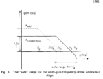
I was reading the Bult and Geelen paper mentioned in another thread here and I was confused by figure 5 in the paper.

2) if the answer to first question is yes, shouldn't ω4 here be ideally higher than ω5 and lower than ω6?
reddit.PNG
 

The question can better understood with a schematic of cascaded amplifier topology.
 

The question can better understood with a schematic of cascaded amplifier topology.

This is the op-amp circuit
reddit.PNG

It is from the paper by Bult and Geelen on high gain, fast settling opamps.

The main stage is a folded cascode amplifier. the 2 folded cascode with pmos input transistors are the auxiliary amplifiers. The current sources are also realized as cascoded structures with additional gain.
 

GBW of aux opamps has to be equal to dominant pole of main opamp. In other way You get zero (if GBW is lower) or additional pole if it is higher.
It results with auxilliary amps dominant pole location equal to main opamp dominant pole divide by aux opamp gain.
 

GBW of aux opamps has to be equal to dominant pole of main opamp. In other way You get zero (if GBW is lower) or additional pole if it is higher.
It results with auxilliary amps dominant pole location equal to main opamp dominant pole divide by aux opamp gain.

so if I understand you right the GBW of aux op-amps should ideally be equal to the 3dB bandwidth of the main op-amp? The reason I thought that the GBW of the aux op-amps should be larger than the main op-amp because of the following lecture from Berkeley:

https://www.youtube.com/watch?v=h_sGTkYUoN4&t=7m30s
 

With aux amp GBW=-3dB BW of main opamp, You get a single pole transfer function in frequency interest. With GBW_aux > GBW_main You will have to move a non-dominant pole of opamp by Aux_Gain_in_dB/20 frequency decades further than in the case without gain boosting to ensure stability. It means, that if your aux amp gain is 60dB and GBW of main opamp is 10MHz, the non-dominant pole has to be placed not beyond 30MHz but 30GHz, to achieve 72° of phase margin!! Make a simple calculations to check it.
 
  • Like
Reactions: d123

    d123

    Points: 2
    Helpful Answer Positive Rating
Status
Not open for further replies.

Similar threads

Part and Inventory Search

Welcome to EDABoard.com

Sponsor

Back
Top