makarand123
Newbie level 2
HI guys
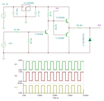
I am working on a PLC whose output is in sink mode(so o/p is not generated till plc is connected in sink mode).Hence I have to extract the required PWM output from PLC using some kind of PNP transistor .The sink type output connections for PLC are as in the following figure . The output on PLC is 24v and also the battery in sink circuit is 24 v(available on plc see fig)
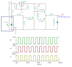
The PWM generated is of 24V and is to be used to drive a Sg-90 servo which requires 5V output so i have designed following circuit and explained the connections in respect to PLC. Target is getting 5v pwm (extracted from PLC).But PNP transistors available can't withstand Vbe over 7-8V.In this Case the Vbe is 24 v (as plc o/p goes low).so the transistor gets shorted easily.
Mosfet also can’t be used as max gate-source voltage is only around 8V.
Major problems
1)servo has pwm port, power,GND
Hence I can’t give PLC’s PWM to the servo by using the resistor divider network as sink type of circuit is not created.
2)cant reduce the PLC’s 24v o/p and external 24 V supply
Please suggest me some other things in place of the transistor.
Advanced Thanks for the Help!


I am working on a PLC whose output is in sink mode(so o/p is not generated till plc is connected in sink mode).Hence I have to extract the required PWM output from PLC using some kind of PNP transistor .The sink type output connections for PLC are as in the following figure . The output on PLC is 24v and also the battery in sink circuit is 24 v(available on plc see fig)
The PWM generated is of 24V and is to be used to drive a Sg-90 servo which requires 5V output so i have designed following circuit and explained the connections in respect to PLC. Target is getting 5v pwm (extracted from PLC).But PNP transistors available can't withstand Vbe over 7-8V.In this Case the Vbe is 24 v (as plc o/p goes low).so the transistor gets shorted easily.
Mosfet also can’t be used as max gate-source voltage is only around 8V.
Major problems
1)servo has pwm port, power,GND
Hence I can’t give PLC’s PWM to the servo by using the resistor divider network as sink type of circuit is not created.
2)cant reduce the PLC’s 24v o/p and external 24 V supply
Please suggest me some other things in place of the transistor.
Advanced Thanks for the Help!
Last edited by a moderator: