Continue to Site

Welcome to EDAboard.com

Welcome to our site! EDAboard.com is an international Electronics Discussion Forum focused on EDA software, circuits, schematics, books, theory, papers, asic, pld, 8051, DSP, Network, RF, Analog Design, PCB, Service Manuals... and a whole lot more! To participate you need to register. Registration is free. Click here to register now.

Design D Flip Flop by using NMOS PMOS in 130nm technology and connect to PLL

Status
Not open for further replies.

minhhoa2310

Newbie level 4
Joined
Dec 16, 2016
Messages
7
Helped
0
Reputation
0
Reaction score
0
Trophy points
1
Activity points
58
Sorry, I'm newbie. I have 3 problems that can not be solve more than 1 week. I need solve as soon as possible.

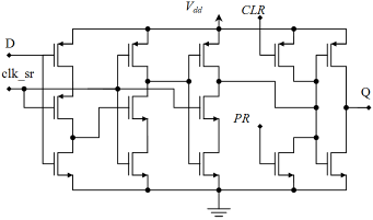
Firstly, please help me draw schematic in Cadence about D Flip Flop using NMOS and PMOS or something like these.

Secondly, please help me draw schematic 8-bit register with that D-FF.

Thirdly, please help me how I can connect PLL (Phased-Locked-Loop) with a 8-bit register which contains the input value to choose frequency in PLL ( Ex: when I choose 00000001, frequency is 50Hz; 00000010, frequency is 100Hz...)

Thank you very much.
 

I doubt you are going to have anyone draw the schematic for you.

1. If you don't know how to use the cadence tools:
Here is the results of searching for "cadence schematic tutorial"

2. If you don't know what a nmos flip flop circuit looks like:
Here is the search results of "nmos flip flop images"

3. If you don't know what google is:
What is google...where is google search...how to use google?

Excuse me ! I'm newbie and before I write this post, I surfed everthing related to my problem, but it just related to digital circuit not analog.

Anyway, I wanna give you "thank you so much for your comment".
 

To make it from mosfets (analog components), a D flip-flop looks like this. Other configurations may be found besides this, of course.

5564770800_1482123472.png


[found at www .intechopen .com /source /html /17222 /media /image19 .png]

So, do you really have to draw that entire circuit eight times and hook them all together? Instead it should be sufficient to draw the usual icon with 4 or 5 terminals.
 

Hi,

but it just related to digital circuit not analog.

In your first post you didn't say anything about "analog".
--> a flipflop usually is digital
--> a 8 bit DFF is digital
--> a PLL is digital (only the filter is a passive -analog- one and the VCO)

Please tell exactely where you see the problems. In my eyes a FF, a DFF and a PLL are very common circuits with more than enough documentation around.

Added:
Your 8 bit DFF to choose output frequency need to act as a "divider" (counter, compare, reset) and needs to be installed in the feedback path of the PLL, so it acts as a "multiplier".
But this is shown and described in any PLL documentation.

Btw: you are talking about relatively low output frequencies with high dynamics (1:255), therefore the use of an NCO instead of a PLL may be more suited.

Klaus
 

To make it from mosfets (analog components), a D flip-flop looks like this. Other configurations may be found besides this, of course.

5564770800_1482123472.png


[found at www .intechopen .com /source /html /17222 /media /image19 .png]

So, do you really have to draw that entire circuit eight times and hook them all together? Instead it should be sufficient to draw the usual icon with 4 or 5 terminals.

Thank you so much.
I have done this circuit but I don't know how to determine Width and Length of D FF? Now I am doing in 130 nm technology.

- - - Updated - - -

Hi,


In your first post you didn't say anything about "analog".
--> a flipflop usually is digital
--> a 8 bit DFF is digital
--> a PLL is digital (only the filter is a passive -analog- one and the VCO)

Please tell exactely where you see the problems. In my eyes a FF, a DFF and a PLL are very common circuits with more than enough documentation around.

Added:
Your 8 bit DFF to choose output frequency need to act as a "divider" (counter, compare, reset) and needs to be installed in the feedback path of the PLL, so it acts as a "multiplier".
But this is shown and described in any PLL documentation.

Btw: you are talking about relatively low output frequencies with high dynamics (1:255), therefore the use of an NCO instead of a PLL may be more suited.

Klaus

Sorry about that, I am doing at Analog desgin.

This problem is related to Analog, but I look for some information, which only show Digital design.
Now, I am using PLL, this is mentor's requirement, it can not be changed.

Please show me block diagram by your drawing.
Please remember, when a person want to choose 50Hz, they will press 00000001, and etc ...

MinhHoa
 

Status
Not open for further replies.

Similar threads

Part and Inventory Search

Welcome to EDABoard.com

Sponsor

Back
Top