Continue to Site

Welcome to EDAboard.com

Welcome to our site! EDAboard.com is an international Electronics Discussion Forum focused on EDA software, circuits, schematics, books, theory, papers, asic, pld, 8051, DSP, Network, RF, Analog Design, PCB, Service Manuals... and a whole lot more! To participate you need to register. Registration is free. Click here to register now.

Can I use Two Timers and a Pot to make Variable PWM ?

Status
Not open for further replies.

Okada

Banned
Joined
Jun 16, 2016
Messages
1,159
Helped
129
Reputation
252
Reaction score
129
Trophy points
63
Activity points
0
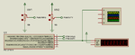
I am using PIC12F1840. INTRC 4 MHz. I want variable frequency and variable duty PWM. Freq range is 9 Hz to 14 Hz and duty 0 to 100%.

Can I use Two Timers and a Pot to make Variable PWM ? or do I need Two timers and two pots ?

Pots are used for ADC. ADC value is converter to timer reload values.

I am planning to do like this.

1. Enable timer 0 and disable timer 1
2. Start Timer 0 for PWM ON period and port bit on from previous timer 1.
3. When Timer 0 interrupt occurs, stop timer 0 and turn off timer 0 and toggle port bit. Start timer 1 for pwm off period.
4. When timer 1 interrupt occurs stop timer 1, turn ON port bit, start timer 0.

repeat 2 to 4 continuously

Read adc value and convert raw adc value to timer 0 on time and timer 1 on time for pwm on and off times.

All suggestions are welcomed.

How many times the port bit turns ON and OFF in 1 sec determines the PWM frequency. Right ?
The duration of PWM On time and PWM Off time setermines the pwm duty. Right ?


Edit:

Single timer can be used.

The PWM On time and Off time timer relaod values are alternately loaded in the timer isr.
 
Last edited:

Hi,

You just need one timer/counter periferal for the PWM generation.

***
With two registers (usually) you can control duty cycle and frequency.

***
you need one/two pusbuttons or a switch to select if you want to adjust freq or d.c.

when "freq" is selected then: ADC --> calculations --> set freq register
when "d.c." is selected then: ADC --> calculations --> set d.c. register

This is done in main loop.
You may use an extra timer for the ADC sampling control.
You may use the PWM timer/counter for ADC sampling control (my recommendation)
or yu may use delay() for ADC sampling control.

Klaus
 

You can generate variable pwm using one timer and one pot also.
1.make port pin ON. start timer with ON time period
2.when it expires load OFF time period to timing registers. And make port pin off

Whenever ADC value gets changed calculate new ON, OFF values for timer registers
 
  • Like
Reactions: Okada

    Okada

    Points: 2
    Helpful Answer Positive Rating
I have confusion related to pwm frequency and pwm duty. Check post #1. Explain them clearly.
 

Hi,
images (7).png
 

Hi,

I´m not familiar with PIC. Doesn´t it have a generating PWM hardware?

If not:
Then software PWM:
* setup timer to trigger an interrupt maybe every 1ms.

* you need one variable "H_per" (HIGH period time)
* you need one variable "L_per" (LOW period)
(both > 0)

ISR:
* decrement counter:
* if not 0: leave the ISR

* 0:
* are you in LOW period? (you could check port state)
* YES: set output high, set counter = H_per
* NO: set output low, set counter = L_per
* leave ISR
***

* special care if you really need 0% and 100% duty cycle. (maybe disable this interrupt and set/clear port pin)

9 Hz means 111 ms: --> L_per + H_per = 111. Low d.c.: L_per=110, H_per = 1. High d.c.: L_per=1, H_per = 110
14 Hz means 71 ms: --> L_per + H_per = 71. Low d.c.: L_per=70, H_per = 1. High d.c.: L_per=1, H_per = 70

Klaus
 

I am not getting variable duty pwm. Proteus file attached.


I need frequency 9 Hz to 14 Hz

Duty 0 to 100%

PWM FREQ ADC calculation.
Assuming 50% duty

T9Hz = 111 ms
T14Hz = 71.42 ms

TMR0 value varies from 39 to 117 for 111/2 ms to 71.42/2 ms

Linear Regression

https://www.graphpad.com/quickcalcs/linear1/

ADC value 0 = 39
ADC value 1023 = 117

Code:
timer_value = (0.07625 * ADC_Read(0) + 39.00) * 2.0


Code C - [expand]
1
2
3
4
5
6
7
8
9
10
11
12
13
14
15
16
17
18
19
20
21
22
23
24
25
26
27
28
29
30
31
32
33
34
35
36
37
38
39
40
41
42
43
44
45
46
47
48
49
50
51
52
53
54
55
56
57
58
59
60
unsigned int timer_value = 0;
unsigned int pwm_on_time_timer_value = 0, pwm_off_time_timer_value = 0;
double duty = 0;
unsigned char myFlags = 0;
 
sbit pwm_toggle_flag at myFlags.B0;
 
//Timer0
//Prescaler 1:256; TMR0 Preload = 39; Actual Interrupt Time : 55.552 ms
//Place/Copy this part in declaration section
void InitTimer0() {
    OPTION_REG = 0x87;
    TMR0 = 39;
    INTCON = 0xA0;
} 
 
void Interrupt() {       
    if((TMR0IE_bit) && (TMR0IF_bit)) {        
        //Enter your code here
        pwm_toggle_flag = ~pwm_toggle_flag;
        
        if(pwm_toggle_flag == 1) {
           TMR0 = pwm_on_time_timer_value;
           LATA2_bit = 1;
        }
        else if(pwm_toggle_flag == 0) {
           TMR0 = pwm_off_time_timer_value;
           LATA2_bit = 0;
        }       
        
        TMR0IF_bit = 0;       
    }
}
 
void main() {
        
    OSCCON = 0b01101011;  //OSC - INTRC 4 MHz
    OSCTUNE = 0x00;
    
    CM1CON0 = 0x00;       //Disable Comparators
    ADCON1 = 0b11010000;    
    ANSELA = 0x03;        //Disable ADC
    TRISA = 0x03;         //PORTA all pins digital output
    PORTA = 0x00;         //Clear PORTA - Used for Inputs
    LATA = 0x00;          //Clear PORTA Latch Regsisters - Used for Output
    
    InitTimer0();        
    
    while(1) {
         asm clrwdt       //Clear WDT
         
         timer_value = (0.07625 * ADC_Read(0) + 39.00) * 2.0;
         Delay_us(20);
         duty = ADC_Read(1) * 0.09776;
         Delay_us(20);
         pwm_on_time_timer_value = timer_value * duty / 100.0;
         pwm_off_time_timer_value = timer_value - pwm_on_time_timer_value;         
         
    }
}


Attachments

  • PWM Variable Frequency, Variable Duty - Using Timer0 and 2 Ch ADC.rar
    48 KB · Views: 53

Hi,

you are going a different approach....

Now you use two pots
and you don´t generate interrupts every 1ms.

For sure you can´t use my calculations then.

****
I´m not familiar with your microcontroller, therefore you have to tell:
* is it an 8 bit timer or an 16 bit timer?
* how long is one timer_clock_tick_time with your selected 256 prescaler?

***

It seems you want to generate one timer interrupt for each PWM signal edge.
Then the PWM frequency is: f = 1 / (t_high + t_low)
(t_high + t_low) is one perid time

calculating back:
you want to know period time:
period_time = 1/f

example: 14Hz: period time = 0.07142 s

if you want to know the high_time: t_high = d.c. x period_time
if you want to know the low_time: t_low = period_time - high_time

...to calculate the (integer) timer values you just need divide those times by your timer_clock_tick_time

***
After that we can optimize some steps...

Klaus
 

I used the easier method. I need two pots to vary frequency and duty. Code is correct. It is working fine. See attached simulation and video. Frequency is correct and also duty.

Duty was inverted. Fixed it.

Yes, Timer0 is an 8-bit timer and I used mikroe timer calculator tool to get the code for timer interrupt.


Code C - [expand]
1
2
3
4
5
6
7
8
9
10
11
12
13
14
15
16
17
18
19
20
21
22
23
24
25
26
27
28
29
30
31
32
33
34
35
36
37
38
39
40
41
42
43
44
45
46
47
48
49
50
51
52
53
54
55
56
57
58
59
60
unsigned int timer_value = 0;
unsigned int pwm_on_time_timer_value = 0, pwm_off_time_timer_value = 0;
double duty = 0;
unsigned char myFlags = 0;
 
sbit pwm_toggle_flag at myFlags.B0;
 
//Timer0
//Prescaler 1:256; TMR0 Preload = 39; Actual Interrupt Time : 55.552 ms
//Place/Copy this part in declaration section
void InitTimer0() {
    OPTION_REG = 0x87;
    TMR0 = 39;
    INTCON = 0xA0;
} 
 
void Interrupt() {       
    if((TMR0IE_bit) && (TMR0IF_bit)) {        
        //Enter your code here
        pwm_toggle_flag = ~pwm_toggle_flag;
        
        if(pwm_toggle_flag == 1) {
           TMR0 = pwm_off_time_timer_value;
           LATA2_bit = 1;
        }
        else if(pwm_toggle_flag == 0) {
           TMR0 = pwm_on_time_timer_value;
           LATA2_bit = 0;
        }       
        
        TMR0IF_bit = 0;       
    }
}
 
void main() {
        
    OSCCON = 0b01101011;  //OSC - INTRC 4 MHz
    OSCTUNE = 0x00;
    
    CM1CON0 = 0x00;       //Disable Comparators
    ADCON1 = 0b11010000;    
    ANSELA = 0x03;        //Disable ADC
    TRISA = 0x03;         //PORTA all pins digital output
    PORTA = 0x00;         //Clear PORTA - Used for Inputs
    LATA = 0x00;          //Clear PORTA Latch Regsisters - Used for Output
    
    InitTimer0();        
    
    while(1) {
         asm clrwdt       //Clear WDT
         
         timer_value = (0.07625 * ADC_Read(0) + 39.00) * 2.0;
         Delay_us(20);
         duty = ceil((double)ADC_Read(1) * 0.09776);
         Delay_us(20);
         pwm_on_time_timer_value = timer_value * duty / 100.0;
         pwm_off_time_timer_value = timer_value - pwm_on_time_timer_value;         
         
    }
}


Attachments

  • PWM VF, VD.rar
    270 KB · Views: 49

Hi,

be carefull with "toggle".

If it begins with the wrong (or intermediately forgets it´s current) state, then duty cycle may be inversed.

I recommend to use "absolute" programming rather than your "relative" programming.

Klaus
 

Project is working in hardware. See attached image.
 

Attachments

  • Signals.png
    Signals.png
    38.5 KB · Views: 67

Explain about absolute programming and relative programming.

- - - Updated - - -

Here are the correct signals.
 

Attachments

  • Signals.png
    Signals.png
    43.6 KB · Views: 69

Hi,

imagine you want a 10% duty cycle with a 10 Hz signal:

ON time = 10ms
OFF time = 90ms

If you just generate (toggle) interrupt in the order: 10ms, 90ms, 10ms, 90ms, 10ms, 90 ms....

now imagine the output initally is high:
Resulting in: 10ms HIGH, 90ms LOW 10ms HIGH, 90ms LOW.... correct so far..

but now imagine the output initially is LOW when you start the sequence:
Resulting in: 10ms LOW, 90ms HIGH, 10ms LOW, 90ms HIGH.... now you have continously 90% duty cycle instead of 10%!

Or imagine you just miss one single "toggle".. the result is that the duty cycle jumps from 10% to 90% and stays there until the next missing event when it jumps back to 10%.

***
To avoid this I recommend to read back the port state and decide what to do.

If it was HIGH before: then set it LOW and set the timing for the LOW period
If it was LOW before: then set it HIGH and set the timing for the HIGH period
(important is to set the correct timing)

If it now misses one interrupt it just results in two HIGH phases (or LOW phases) after each other to self correct for the missing event. But after that it runs with the desired duty cycle.

Klaus
 

Thank you for explaining. Now I understood clearly.
 

In 100% duty PWM frequency suddenly becomes 0 ?
 

Hi,

In 100% duty PWM frequency suddenly becomes 0 ?
What about 0% duty cycle? ;-)

Saying: In the night every cat is black.

Klaus
 

Yes, both 0 and 100% duties give 0 frequency.

In PIC 100% duty PWM is 5V and 0%duty PWM is 0V and frequency of DC is 0 and hence 0% and 100% duty PWM have 0 frequency.

- - - Updated - - -

For frequency calculations are like this

T9Hz = 111ms

T14Hz = 71.43ms

Timer1, Fosc = 4 MHz, PIC16, Timer Calculator tool is used to calculate TMR1H and TMR1L values

For

T9Hz it is 10036

T14Hz it is 29826

ADC is used to convert RA0 value to Timer reload value

This tool is used to get the equation for below data

https://www.graphpad.com/quickcalcs/linear1/

X Y

0 10036
1023 29826

Equation is

Code:
	timer_reload_value = 19.35 * ADC_Read(0) + 10036;

For PWM duty ADC1 is used, RA1

Duty varies from 0 to 100%

Equation is

Code:
duty = ADC_Read(1) * 0.09776;

eg: 1023 * 0.09776 = 100.008

pwm_on_time and pwm_off_time reload values are calculated.

Now, code is not working as needed.

Simulation file included.

What is the problem ?


Edit:

replaced

Code:
TMR0IF_bit = 0;

in isr by

Code:
TMR1IF_bit = 0;

Now I am getting pwm signal but freq and duty are not correct.


Code C - [expand]
1
2
3
4
5
6
7
8
9
10
11
12
13
14
15
16
17
18
19
20
21
22
23
24
25
26
27
28
29
30
31
32
33
34
35
36
37
38
39
40
41
42
43
44
45
46
47
48
49
50
51
52
53
54
55
56
57
58
59
60
61
62
63
64
65
66
67
68
69
#define Lo(param) ((char *)&param)[0]
#define Hi(param) ((char *)&param)[1]
 
double timer_value = 0;
unsigned int pwm_on_time_timer_value = 0, pwm_off_time_timer_value = 0;
double duty = 0;
unsigned char myFlags = 0;
 
sbit pwm_toggle_flag at myFlags.B0;
 
//Timer1
//Prescaler 1:2; TMR1 Preload = 26536; Actual Interrupt Time : 78 ms
//Place/Copy this part in declaration section
void InitTimer1() {    
    T1CON = 0x11;
    TMR1IF_bit = 0;
    TMR1H = 0x67;
    TMR1L = 0xA8;
    TMR1IE_bit = 1;
    INTCON = 0xC0;
}
 
void Interrupt() {       
    if((TMR1IE_bit) && (TMR1IF_bit)) {        
        //Enter your code here
                
        if(LATA2_bit == 0) {
           TMR1H = Hi(pwm_off_time_timer_value);
           TMR1L = Lo(pwm_off_time_timer_value);
           
           LATA2_bit = 1;
        }
        else if(LATA2_bit == 1) {
           TMR1H = Hi(pwm_on_time_timer_value);
           TMR1L = Lo(pwm_on_time_timer_value);
           
           LATA2_bit = 0;
        }       
        
        TMR0IF_bit = 0;       
    }
}
 
void main() {
        
    OSCCON = 0b01101011;  //OSC - INTRC 4 MHz
    OSCTUNE = 0x00;
    
    CM1CON0 = 0x00;       //Disable Comparators
    ADCON1 = 0b11010000;    
    ANSELA = 0x03;        //Disable ADC
    TRISA = 0x03;         //PORTA all pins digital output
    PORTA = 0x00;         //Clear PORTA - Used for Inputs
    LATA = 0x00;          //Clear PORTA Latch Regsisters - Used for Output
    
    InitTimer1();        
    
    while(1) {
         asm clrwdt       //Clear WDT
         
         timer_value = 19.35 * ADC_Read(0) + 10036;                   
         Delay_us(20);
         duty = ceil((double)ADC_Read(1) * 0.09776);
         Delay_us(20);
         pwm_on_time_timer_value = ceil(timer_value * duty / 100.0);
         pwm_off_time_timer_value = ceil(timer_value - pwm_on_time_timer_value);         
         
    }
}


Attachments

  • PWM VF, VD - Fixed.rar
    53 KB · Views: 40
  • pwm.png
    pwm.png
    21.8 KB · Views: 74
Last edited:

Hi,

Now, code is not working as needed.
... is useless, because it doesn´t describe anything.
--> give a detailed error description.

... but freq and duty are not correct.
... is useless, because it doesn´t describe anything.
--> give a detailed error description.


Code:
    while(1) {
         asm clrwdt       //Clear WDT
         
         timer_value = 19.35 * ADC_Read(0) + 10036;                   
         Delay_us(20);
         duty = ceil((double)ADC_Read(1) * 0.09776);
         Delay_us(20);
         pwm_on_time_timer_value = ceil(timer_value * duty / 100.0);
         pwm_off_time_timer_value = ceil(timer_value - pwm_on_time_timer_value);

here you update the values about every 50 microseconds.
If your PWM frequency is 9Hz, then you update the values about 2000 times within one PWM period. It makes no sense.

Max. Update rate should be one PWM period. Simply synchronize it with the PWM period. --> Set a flag in ISR every PWM period. In Main loop check this flag, If set, then update values and clear flag.

Klaus
 

PWM frequency I am getting is 5 Hz in the frequency counter. Duty is not varying.

I am loading TMR1H and TMR1L registers in ISR.
 

If I vary the FREQ Pot the frequency doesn't change. It remains fluctuating 4 or 5 Hz instead of 9 Hz to 14 Hz.

ADC value 0 = 9 Hz
ADC value 1023 = 14 Hz

needed.

If I vary DUTY pot the duty varies only a little. It should vary 0 to 100%.
 

Status
Not open for further replies.

Similar threads

Part and Inventory Search

Welcome to EDABoard.com

Sponsor

Back
Top