Continue to Site

Welcome to EDAboard.com

Welcome to our site! EDAboard.com is an international Electronics Discussion Forum focused on EDA software, circuits, schematics, books, theory, papers, asic, pld, 8051, DSP, Network, RF, Analog Design, PCB, Service Manuals... and a whole lot more! To participate you need to register. Registration is free. Click here to register now.

How to configure Xilinx SPI IP as Slave

Status
Not open for further replies.

beginner_EDA

Full Member level 4
Joined
Aug 14, 2013
Messages
191
Helped
0
Reputation
0
Reaction score
0
Trophy points
1,296
Activity points
3,854
Hi,
How to configure Xilinx SPI IP as Slave.
https://www.xilinx.com/support/docu...tion/axi_quad_spi/v3_2/pg153-axi-quad-spi.pdf

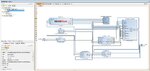
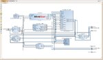
As mentioned in page 84, I unchecked "Enable master mode" and using standard configuration. See Block diagram in attachment.

I don't want to write SPI flash but just to communicate with external spi Master.

and use following code.
Code:
******************************************************************************/
/***************************** Include Files *********************************/
#include "xparameters.h" /* XPAR parameters */
#include "xspi.h" /* SPI device driver */
#include "xspi_l.h"
/************************** Constant Definitions *****************************/
/*
* The following constants map to the XPAR parameters created in the
* xparameters.h file. They are defined here such that a user can easily
* change all the needed parameters in one place.
*/
#define SPI_DEVICE_ID XPAR_SPI_0_DEVICE_ID
 

/***************** Macros (Inline Functions) Definitions *********************/

/************************** Function Prototypes ******************************/
int SpiPolledExample(XSpi *SpiInstancePtr, u16 SpiDeviceId);
/************************** Variable Definitions *****************************/
/*
* The instances to support the device drivers are global such that the
* are initialized to zero each time the program runs.
*/
static XSpi SpiInstance; /* The instance of the SPI device */
/*
* The following variables are used to read and write to the Spi device, they
* are global to avoid having large buffers on the stack.
*/
u8 ReadBuffer;
u8 WriteBuffer;

/*****************************************************************************/
/**
*
* Main function to call the Spi Polled example.
*
* @param None
*
* @return XST_SUCCESS if successful, otherwise XST_FAILURE.
*
* @note None
*
******************************************************************************/
int main(void)
{
int Status;
/*
* Run the Spi Polled example.
*/
Status = SpiPolledExample(&SpiInstance, SPI_DEVICE_ID);
if (Status != XST_SUCCESS) {
return XST_FAILURE;
}
return XST_SUCCESS;
}
/*****************************************************************************/
/**
*
* This function does a minimal test on the Spi device and driver as a
* design example. The purpose of this function is to illustrate how to use
* the XSpi component using the polled mode.
*
* This function sends data and expects to receive the same data.
*
*
* @param SpiInstancePtr is a pointer to the instance of Spi component.
* @param SpiDeviceId is the Device ID of the Spi Device and is the
* XPAR_<SPI_instance>_DEVICE_ID value from xparameters.h.
*
* @return XST_SUCCESS if successful, otherwise XST_FAILURE.
*
* @note
*
* This function contains an infinite loop such that if the Spi device is not
* working it may never return.
*
******************************************************************************/
int SpiPolledExample(XSpi *SpiInstancePtr, u16 SpiDeviceId)
{
int Status;
u32 Count;
u8 Test;
XSpi_Config *ConfigPtr; /* Pointer to Configuration data */
/*
* Initialize the SPI driver so that it is ready to use.
*/
ConfigPtr = XSpi_LookupConfig(SpiDeviceId);
if (ConfigPtr == NULL) {
return XST_DEVICE_NOT_FOUND;
}
Status = XSpi_CfgInitialize(SpiInstancePtr, ConfigPtr,
ConfigPtr->BaseAddress);
if (Status != XST_SUCCESS) {
return XST_FAILURE;
}
/*
* Perform a self-test to ensure that the hardware was built correctly.
*/
Status = XSpi_SelfTest(SpiInstancePtr);
if (Status != XST_SUCCESS) {
return XST_FAILURE;
//xil_printf("xyz\n\r");
}
/*
* Run loopback test only in case of standard SPI mode.
*/
if (SpiInstancePtr->SpiMode != XSP_STANDARD_MODE) {
return XST_SUCCESS;
//xil_printf("xyz\n\r");
}
/*
* Set the Spi device as salve see page 25 and 26
*/
XSpi_SetControlReg(&Spi, 0x02);

/*
* Start the SPI driver so that the device is enabled.
*/
XSpi_Start(SpiInstancePtr);
/*
* Disable Global interrupt to use polled mode operation
*/
XSpi_IntrGlobalDisable(SpiInstancePtr);
/*

/*
* Transmit/receive the 1 byte of data.
*/
XSpi_Transfer(SpiInstancePtr, WriteBuffer, ReadBuffer, 1);

It is also not clear to me, what is difference between
XSpi_Transfer(SpiInstancePtr, WriteBuffer, ReadBuffer, 1);
XSpi_Transfer(SpiInstancePtr, ReadBuffer, ReadBuffer, 1);

and
XSpi_WriteReg(BaseAddress, RegOffset, RegisterValue);
XSpi_ReadReg(BaseAddress, RegOffset);

to read and write?
When we use which one?
 

Attachments

  • blockdiagram.jpg
    blockdiagram.jpg
    259 KB · Views: 280

You have what looks like two other threads on this same subject.

The documentation for the AXI Quad SPI is very thin on the Enable Master Mode check box and what it does when NOT checked.

It definitely does not reverse the direction of the AXI bus, therefore I don't think it turns the SPI into a slave device that bridges to a master AXI. I'm not entirely sure it even works considering the lack of information provided.

The documentation pretty much is entirely on the functionality of using the core as an AXI slave to SPI master bridge. There is virtually nothing in the documentation describing going the other direction (SPI slave to AXI master bridge).

Given the time you've spent on this you could have written your own SPI slave to AXI master bridge.
 
Given the time you've spent on this you could have written your own SPI slave to AXI master bridge.

Hi I did this already and RX part(mosi from master) is correct but Tx part(miso to master) become half clock right shifted corresponding to SPI clock and don't know how to fix it.
I want to actually sync Tx part(miso to master) with SPI clock.

Here is how I tried:


Code VHDL - [expand]
1
2
3
4
5
6
7
8
9
10
11
12
13
14
15
16
17
18
19
20
21
22
23
24
25
26
27
28
29
30
31
32
33
34
35
36
37
38
39
40
41
42
43
44
45
46
47
48
49
50
51
52
53
54
55
56
57
58
59
60
61
62
63
64
65
66
67
68
69
70
71
72
73
74
75
76
77
78
79
80
81
82
83
84
85
86
87
88
89
90
91
92
93
94
95
96
97
98
99
100
101
102
103
104
105
106
107
108
109
110
111
112
113
114
115
116
117
118
119
120
121
122
123
124
125
126
127
128
129
130
131
132
133
134
135
136
137
138
139
140
141
142
143
144
145
146
147
148
149
150
151
152
153
154
155
156
157
158
159
160
161
162
163
164
165
166
167
168
169
170
171
172
173
174
175
176
177
178
179
180
181
182
183
184
185
186
187
188
189
--Copyright 1986-2015 Xilinx, Inc. All Rights Reserved.
----------------------------------------------------------------------------------
--Tool Version: Vivado v.2015.2 (win64) Build 1266856 Fri Jun 26 16:35:25 MDT 2015
--Date        : Thu Nov 10 16:36:39 2016
--Host        : WKS-FASHE running 64-bit Service Pack 1  (build 7601)
--Command     : generate_target design_1_wrapper.bd
--Design      : design_1_wrapper
--Purpose     : IP block netlist
----------------------------------------------------------------------------------
library IEEE;
use IEEE.STD_LOGIC_1164.ALL;
use IEEE.STD_LOGIC_ARITH.ALL;
use IEEE.STD_LOGIC_UNSIGNED.ALL;
--use ieee.numeric_std.all;
library UNISIM;
use UNISIM.VCOMPONENTS.ALL;
entity spi_top is
  port (
   -- dip_switches_4bits_tri_i : in STD_LOGIC_VECTOR ( 2 downto 0 );
   XADC_GPIO_0 : in std_logic; --mosi
   XADC_GPIO_2 : in std_logic; --slave select
   XADC_GPIO_3 : in std_logic; -- spi clock
  --  gpio_rtl_tri_o : out STD_LOGIC_VECTOR ( 0 to 0 );
  XADC_GPIO_1 : out std_logic; --miso
    reset : in STD_LOGIC;
    rs232_uart_rxd : in STD_LOGIC;
    rs232_uart_txd : out STD_LOGIC;
    sys_diff_clock_clk_n : in STD_LOGIC;
    sys_diff_clock_clk_p : in STD_LOGIC
  );
end spi_top;
 
architecture STRUCTURE of spi_top is
  component design_1 is
port (
  rs232_uart_rxd : in STD_LOGIC;
  rs232_uart_txd : out STD_LOGIC;
  dip_switches_4bits_tri_i : in STD_LOGIC_VECTOR ( 7 downto 0 );
  dip_switches_4bits_0_tri_o : out STD_LOGIC_VECTOR ( 7 downto 0 );
  out_clk : out STD_LOGIC;
  out_clk_1 : out STD_LOGIC;
   gpio_rtl_tri_i : in STD_LOGIC_VECTOR ( 0 to 0 );
   gpio_rtl_0_tri_i : in STD_LOGIC_VECTOR ( 0 to 0 );
 --  reset_gpio : out STD_LOGIC_VECTOR ( 0 to 0 );
  sys_diff_clock_clk_n : in STD_LOGIC;
  sys_diff_clock_clk_p : in STD_LOGIC;
  reset : in STD_LOGIC
);
end component design_1;
 
signal  clock_rtl1 : std_logic:='0';
signal  clock_rtl2 : std_logic;
signal out_clk_p : std_logic;
signal out_clk_p1 : std_logic:='0';
signal count1m : std_logic_vector(3 downto 0):="0000";
signal count1mp : std_logic_vector(3 downto 0):="0000";
 
signal mosi_8bit: std_logic_vector (7 downto 0);
signal miso_8bit: std_logic_vector (7 downto 0);
signal miso_8bit_new: std_logic_vector (7 downto 0);
signal miso_int: std_logic_vector (7 downto 0);
signal count :STD_LOGIC_VECTOR (2 downto 0) := "000";
signal control, control1, clk_out, clk_out1: std_logic;
signal gpio1: std_logic;
signal gpio2: std_logic;
signal gpio3: std_logic;
signal gpio4: std_logic;
signal gpio_int: std_logic;
signal int_ctrl:std_logic;
signal reset_gpio_int : STD_LOGIC_VECTOR ( 0 to 0 );
signal count_natural : natural:=7;
signal XADC_GPIO_0_dly1: std_logic;
signal XADC_GPIO_1_dly1: std_logic;
signal XADC_GPIO_2_dly1: std_logic;
signal XADC_GPIO_3_dly1: std_logic;
begin
gpio1 <=  XADC_GPIO_0;
--gpio2 <=gpio_int;
 XADC_GPIO_1 <= gpio2;
 miso_8bit_new <= miso_8bit(0) & miso_8bit(1) & miso_8bit(2) & miso_8bit(3) & miso_8bit(4) & miso_8bit(5) & miso_8bit(6) & miso_8bit(7);
 
spi_slave_mosi:process(XADC_GPIO_3) 
begin
 if rising_edge(XADC_GPIO_3) then
     -- gpio1 <=  XADC_GPIO_0;
      if XADC_GPIO_2 = '0' then
         mosi_8bit(0) <= gpio1;
         mosi_8bit(1) <= mosi_8bit(0);
         mosi_8bit(2) <= mosi_8bit(1);
         mosi_8bit(3) <= mosi_8bit(2);
         mosi_8bit(4) <= mosi_8bit(3);
         mosi_8bit(5) <= mosi_8bit(4);
         mosi_8bit(6) <= mosi_8bit(5);
         mosi_8bit(7) <= mosi_8bit(6);
         end if;
  end if;     
end process;


control_slave_mosi:process(clock_rtl1) 
begin
 if rising_edge(clock_rtl1) then
          int_ctrl <=  XADC_GPIO_2;
         if (int_ctrl = '0' and  XADC_GPIO_2 = '1' ) then
          control <= '1';
          else
          control <= '0';
         end if;     
  end if;     
end process;
 
spi_slave_miso:process(XADC_GPIO_3) 
begin
 if rising_edge(XADC_GPIO_3) then
     -- gpio1 <=  XADC_GPIO_0;
      if XADC_GPIO_2 = '0'  then
       --  gpio2 <= miso_8bit(count_natural);
       gpio2 <= miso_int(count_natural);
       -- count_natural := count_natural + 1;
          count_natural <= count_natural - 1;
        if (count_natural=0) then
        -- count_natural := 0;
           count_natural <= 7;
         end if;
       end if;
  end if;     
end process;
 
 
spi_halfclk_miso:process(out_clk_p1) 
--variable count_natural : natural:=0;
begin
 if rising_edge(out_clk_p1) then
       miso_int <= miso_8bit;
 
  end if;     
end process;
 
 
clk_1mhz:process (clock_rtl2)
    begin
    if rising_edge (clock_rtl2) then
        if count1m=4 then
        clock_rtl1 <=  not clock_rtl1;
        count1m <= "0000";
        else
        count1m <= count1m + '1';
        end if;
    
    end if;
    
    end process;
 
clk_1mhz_p:process (out_clk_p)
    begin
    if rising_edge (out_clk_p) then
        if count1m=4 then
        out_clk_p1 <=  not out_clk_p1;
        count1mp <= "0000";
        else
        count1mp <= count1mp + '1';
        end if;
    
    end if;
    
    end process;
 
 
design_inst:  design_1
     port map (
      dip_switches_4bits_tri_i(7 downto 0) => mosi_8bit,
      dip_switches_4bits_0_tri_o(7 downto 0) =>  miso_8bit,
      gpio_rtl_tri_i(0) => control,
       gpio_rtl_0_tri_i(0) => XADC_GPIO_3,
      reset => reset,
     -- reset_gpio(0) => reset_gpio_int(0),
      rs232_uart_rxd => rs232_uart_rxd,
      rs232_uart_txd => rs232_uart_txd,
      sys_diff_clock_clk_n => sys_diff_clock_clk_n,
      sys_diff_clock_clk_p => sys_diff_clock_clk_p,
      out_clk => clock_rtl2,
       out_clk_1 => out_clk_p
    );


end STRUCTURE;


component design_1 is the block design I created to read and write the value by microblaze via GPIO.

and corresponding c code:
Code:
#include <stdio.h>
#include "platform.h"
#include "xgpio.h"
#include "xparameters.h"
#include "microblaze_sleep.h"

void print(char *str);

//declare an XGpio and XGpio instance
XGpio GPIO_0;
XGpio_Config GPIO_0_conf;
XGpio GPIO_1;
XGpio_Config GPIO_1_conf;


int main()
{
  //  GPIO 0

	GPIO_0_conf.BaseAddress = XPAR_AXI_GPIO_0_BASEADDR;
    GPIO_0_conf.DeviceId = XPAR_AXI_GPIO_0_DEVICE_ID;
    GPIO_0_conf.InterruptPresent = XPAR_GPIO_0_INTERRUPT_PRESENT;
    GPIO_0_conf.IsDual = XPAR_GPIO_0_IS_DUAL;

    //Initialize the XGpio instance
    XGpio_CfgInitialize(&GPIO_0, &GPIO_0_conf, GPIO_0_conf.BaseAddress);
    XGpio_SetDataDirection(&GPIO_0, 1, 0xff);
    XGpio_SetDataDirection(&GPIO_0, 2, 0x01);


    // GPIO 1

       GPIO_1_conf.BaseAddress = XPAR_AXI_GPIO_1_BASEADDR;
       GPIO_1_conf.DeviceId = XPAR_AXI_GPIO_1_DEVICE_ID;
       GPIO_1_conf.InterruptPresent = XPAR_GPIO_1_INTERRUPT_PRESENT;
       GPIO_1_conf.IsDual = XPAR_GPIO_1_IS_DUAL;

       //Initialize the XGpio instance
       XGpio_CfgInitialize(&GPIO_1, &GPIO_1_conf, GPIO_1_conf.BaseAddress);
       XGpio_SetDataDirection(&GPIO_1, 1, 0x00);
       XGpio_SetDataDirection(&GPIO_1, 2, 0x01);


    init_platform();
    print("Hello World\n\r");

    u32 input;
    u32 read;
     u32 control;
    // check = 0x3;
    while(1){

    	   //Read the switches values
    	      //  input = XGpio_DiscreteRead(&GPIO_0, 1);
              //  read = (input & 0xff);

                xil_printf("outjustprint\n" );
           //   xil_printf("out = %x\n", XGpio_DiscreteRead(&GPIO_0, 1) );
                if(( XGpio_DiscreteRead(&GPIO_0, 2) & 0x01))
		{
    	        xil_printf("read = %x\n", XGpio_DiscreteRead(&GPIO_0, 1));


		}

           //     if(( XGpio_DiscreteRead(&GPIO_1, 2) & 0x01) == 0)

                   	XGpio_DiscreteWrite(&GPIO_1, 1, 0x26);

              //  XGpio_DiscreteWrite(&GPIO_1, 1, 0x000000ee);
    }

    return 0;
}
 

Attachments

  • blockdiagram.jpg
    blockdiagram.jpg
    190 KB · Views: 168
Last edited:

Status
Not open for further replies.

Part and Inventory Search

Welcome to EDABoard.com

Sponsor

Back
Top