Continue to Site

Welcome to EDAboard.com

Welcome to our site! EDAboard.com is an international Electronics Discussion Forum focused on EDA software, circuits, schematics, books, theory, papers, asic, pld, 8051, DSP, Network, RF, Analog Design, PCB, Service Manuals... and a whole lot more! To participate you need to register. Registration is free. Click here to register now.

Problem with design of a peak detector

Status
Not open for further replies.

lolxiang

Newbie level 1
Joined
Dec 27, 2012
Messages
1
Helped
0
Reputation
0
Reaction score
0
Trophy points
1,281
Location
Singapore
Activity points
1,295
Hi all

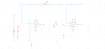
I was designing a peak detector with cadence. I used a very simple structure as shown in the first figure, an op amp drives a MOS diode to charge a hold cap, and feedback ensures the output tracks the input when input is higher.

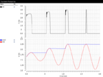
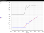
The simulated waveform are as in p1 and p2 where some kind of oscillation is found. The op amp is unity-gain stable with that hold cap, but when I replaced the op amp with an ideal model the oscillation is gone. So I think it is due to the instability of the feedback, but with that diode I have no ideal how to tackle this problem. Any advice is appreciated.
 

Attachments

  • p3.png
    p3.png
    18.7 KB · Views: 79
  • p1.png
    p1.png
    43.1 KB · Views: 69
  • p2.png
    p2.png
    36.5 KB · Views: 63

This indeed look a like stability issue for the opamp. With the probe in place, what is the phase margin and gain margin you obtain? Check with some initial condition on the capacitor, by inserting a voltage source in series with the capacitor.
 

The op amp is unity-gain stable with that hold cap
But apparently not with RC in loop.

Need to tune the loop gain. Simple measure can be series R for hold cap. Unfortunately any solution for smoother track operation will probably worsen the hold performance, unless you can improve the OP GBW.
 

Most opamps have a maximum allowed capacitance that connects directly to its output. I agree that a resistor should be between the output of the opamp and the "rectifier diode".
The frequency is very low so why not use an ordinary silicon diode?

The first opamp does not have a negative supply so when the AC input signal swings negative then the input transistor on the opamp is destroyed. If a negative supply is added then another diode is needed to prevent the output of the opamp from saturating at its maximum negative output voltage.
 

Status
Not open for further replies.

Similar threads

Part and Inventory Search

Welcome to EDABoard.com

Sponsor

Back
Top