Eres_89
Member level 1
Hello everyone.
I'm writing here, because I need help/sugestions.
To the point:
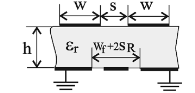
I want to simulate structure, which is presented in attachment (picture no_1.png). Most of popular calculators (such as the TXLine, the AppCAD) has solutions for really typical coupled elements (for e.g. coupled striplines).
I try to simulate no_1 structure in EM simulator such as the HFSS or the AWR Microwave Office but I don't know how can I "measure" even/odd impedances. I have calculated values of Zoo and Zoe but without proper simulator/calculator I cannot design physical structure...
Can you help me with this problem ?
Best Regards
I'm writing here, because I need help/sugestions.
To the point:
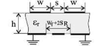
I want to simulate structure, which is presented in attachment (picture no_1.png). Most of popular calculators (such as the TXLine, the AppCAD) has solutions for really typical coupled elements (for e.g. coupled striplines).
I try to simulate no_1 structure in EM simulator such as the HFSS or the AWR Microwave Office but I don't know how can I "measure" even/odd impedances. I have calculated values of Zoo and Zoe but without proper simulator/calculator I cannot design physical structure...
Can you help me with this problem ?
Best Regards