Continue to Site

Welcome to EDAboard.com

Welcome to our site! EDAboard.com is an international Electronics Discussion Forum focused on EDA software, circuits, schematics, books, theory, papers, asic, pld, 8051, DSP, Network, RF, Analog Design, PCB, Service Manuals... and a whole lot more! To participate you need to register. Registration is free. Click here to register now.

[SOLVED] Weird Verilog testbench behavior!

Status
Not open for further replies.

redsees

Junior Member level 1
Joined
Jan 30, 2016
Messages
18
Helped
0
Reputation
0
Reaction score
0
Trophy points
1
Activity points
313
Hello World,

I'm new into the world of Digital Design using FPGA's and PLD's generally.

I was designing a simple code in verilog that does a few bits permutations, when I tested it, always the least significant two bits are x's, I don't know why?

Here is my Verilog code:
Code:
module Generate_Keys(input[0:9] key, input clk, output[0:7] key2);
	reg[0:9] p10_out;
	reg[0:7] tempC, tempD;
	
	always@(posedge clk)
	begin
		// Some permutations
		p10_out = {key[2], key[4], key[1], key[6], key[3], key[9], key[0], key[8], key[7], key[5]};

		// Left Rotation by 3 bits
		tempC = {p10_out[3:4], p10_out[0:2], p10_out[8:9], p10_out[5:7]};

                // More permutations
		tempD = {tempC[5], tempC[2], tempC[6], tempC[3], tempC[7], tempC[4], tempC[9], tempC[8]};
	end
	
	assign key2 = tempD;
	
endmodule


module tb;

	reg clk = 1'b0;
	reg[0:9] key;
	wire[0:7] key2;
	
	always
		#5 clk = ~clk;

	initial
		$monitor("Val = %b\n\nKey2 = %b\n\n",key, key2);
		
	initial
	begin
		key = 10'b1000110100;
		#100;
		$finish;
	end

	Generate_Keys inst0 (.key(key), .clk(clk), .key2(key2));

endmodule

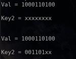
The output is always:
Selection_011.png

The first case is okay, but the problem in the second one, why is the least significant 2 bits are always double x's?
 

Code:
reg[0:7] tempC, tempD;
tempD = {tempC[5], tempC[2], tempC[6], tempC[3], tempC[7], tempC[4], [B][I][COLOR="#FF0000"]tempC[9], tempC[8][/COLOR]};[/I][/B]

There are no tempC[8] or tempC[9] bits.

- - - Updated - - -

As you are new to digital design and Verilog. I advise you not use bit ordering from LSB first, i.e. [0:9], but instead use MSB firrst, i.e [9:0]. If you get in the habit of using your bit ordering you will find your code may be incompatible with others. And if you ever start using VHDL then you will run into even more problems with bit ordering and incompatible assignments.

It's prevalent to order the bits in this fashion as the bit positions correspond to the binary weights:
e.g.
Code:
bit-3210
4'b_1101 = [B][COLOR="#FF0000"]1[/COLOR][/B]*2^3 + [B][COLOR="#FF0000"]1[/COLOR][/B]*2^2 + [B][COLOR="#FF0000"]0[/COLOR][/B]*2^1 + [B][COLOR="#FF0000"]1[/COLOR][/B]*2^0
 
  • Like
Reactions: redsees

    redsees

    Points: 2
    Helpful Answer Positive Rating
IIRC, the 0:N-1 is more common in crypto. For example, the NIST standard for AES has data ordered as 0:127 or 0:255 for the input/output.

I think that the majority of developers would expect N-1:0 as that is very common in CPU/DSP design -- fields that influence most developer's first interactions with digital logic. I think it is justified to use 0:N-1 in cases where some external standard/documentation uses this format.

(0:N-1 is also the VHDL default for literals. Can be very annoying.)
 
  • Like
Reactions: redsees

    redsees

    Points: 2
    Helpful Answer Positive Rating
Aha I see.

I'm really apologizing for such super newbie mistake, I was looking at the whole code and almost was changing every bit of it but didn't actually think that the mistake might have been into the data width.

Thanks again ads-ee and vGoodtimes for your help and advises.
 

Status
Not open for further replies.

Part and Inventory Search

Welcome to EDABoard.com

Sponsor

Back
Top