Continue to Site

Welcome to EDAboard.com

Welcome to our site! EDAboard.com is an international Electronics Discussion Forum focused on EDA software, circuits, schematics, books, theory, papers, asic, pld, 8051, DSP, Network, RF, Analog Design, PCB, Service Manuals... and a whole lot more! To participate you need to register. Registration is free. Click here to register now.

How does my circuit work? (heater, triac, optocoupler, pwm)

Status
Not open for further replies.

I14R10

Full Member level 3
Joined
May 31, 2015
Messages
185
Helped
0
Reputation
0
Reaction score
0
Trophy points
1,296
Activity points
2,750
I built this thing


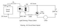
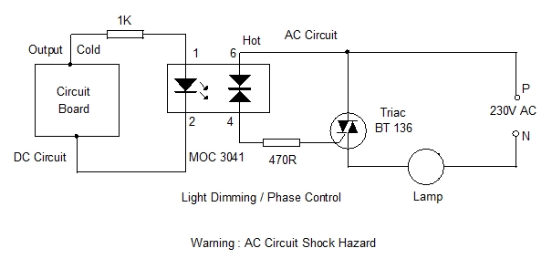
[at dmohankumar .files .wordpress .com /2016 /04 /moc -3041 -circuit .jpg]

except I control the heater at 12V AC and the input to opto-coupler is from atmega8.

And I use 8kHz PWM signal to opto-coupler MOC 3041 to control the power. It seems to be working, but how?

There are around 133 pulses of PWM signal in one period of the AC sine wave signal. It should always be at near 100% on. Because the triac would be turned on very soon after the sine wave crosses zero.

I can explain it if the opto-coupler is turning on the triac according to brightness of the LED from input. That would make sense. If the PWM has 50% duty cycle, the LED within opto coupler would glow at 50% power and the opto coupler would fire triac when sine wave phase is at 90 degrees.

Another explanation is that opto coupler fires only at zero crossing and sometimes the PWM signal happens to be at 0 and sometimes at 1 when zero crossing happens.
 
Last edited:

Re: How does my circuit work?

moc-3041-circuit.jpg

And I use 8kHz PWM signal to opto-coupler MOC 3041 to control the power. It seems to be working
Means what, particularly? Did you check heater power versus pwm?

Another explanation is that opto coupler fires only at zero crossing and sometimes the PWM signal happens to be at 0 and sometimes at 1 when zero crossing happens.
Yes. Problem is that the exact duration zero crossing trigger window isn't very stable. A regular full wave trigger will achieve a better reproducible characteristic.
 

It means that the heater that I have really does heat more when PWM is at duty cycle 75% than when it's at 25%. I did not check power that heater uses as the currents are above 10A at 12V. I don't have equipment to measure it.

- - - Updated - - -

View attachment 133515


Yes. Problem is that the exact duration zero crossing trigger window isn't very stable. A regular full wave trigger will achieve a better reproducible characteristic.

It doesn't need to be very accurate. I just need 0, 25%, 50%, 75%, 100% of power.
 

A source of unpredictable behavior is the ratio between mains and pwm frequency. Your control method will more likely trigger half waves than full waves. At worst only positive or negative cycles, causing DC current and transformer saturation.
 

What would you recommend then, using longer switching times?

1 period on 50Hz is 20ms long, for example:

For 25% power
optocoupler input high for 100ms, low for 300ms (5 periods on)

For 50% power
optocoupler input high for 200ms, low for 200ms (10 periods on)

For 75% power
optocoupler input high for 300ms, low for 100ms (15 periods on)
 

What would you recommend then, using longer switching times?
Yes. Using a cycle in the 0.5 to multiple second range is the usual solution for heater control. It can work even without zero crossing detector.
 

Weird. I had a look with the oscilloscope today. When the opto coupler receives PWM on the gate, I get nice "chopped" sine between triac anodes. When I set duty cycle to 0, there is nice 12V sine across the anodes. As the PWM duty cycle increases, sine wave gets chopped off more and more, meaning it conducts chopped off part.

But when I am switching slowly, I get some weird waveform that looks more like some interference than chopped sine wave.
 

Status
Not open for further replies.

Similar threads

Part and Inventory Search

Welcome to EDABoard.com

Sponsor

Back
Top