Continue to Site

Welcome to EDAboard.com

Welcome to our site! EDAboard.com is an international Electronics Discussion Forum focused on EDA software, circuits, schematics, books, theory, papers, asic, pld, 8051, DSP, Network, RF, Analog Design, PCB, Service Manuals... and a whole lot more! To participate you need to register. Registration is free. Click here to register now.

[SOLVED] Help to make a main adapter for Canon Powershot SX150 IS

Status
Not open for further replies.

jeolex

Member level 2
Joined
Jul 4, 2015
Messages
52
Helped
0
Reputation
0
Reaction score
0
Trophy points
6
Activity points
531
Dear friends,

I have Canon Powershot SX150IS Digital Camera which is run with two AA battery. I am an academician in Faculty of Agriculture. So I wanna observe to cotton leaf movement through different light directions. But my batteries are able to record video maximum a hour. I need 4-5 hours at least. So I try to make a main adapter.

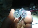
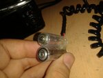
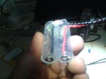
I made a battery like structure for place it inside of battery slot. You can see below.
20161111_205136.jpg20161111_205133.jpg

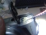
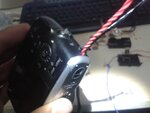
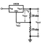
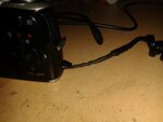
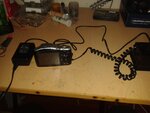
I made it from syringe, bell wire and rove which look like ring and placed on terminal of structure. I have also 5v 3A adapter and a 3.15V regulator circuit that I made it by LM338 max 5A regulator. Everything is ok about circuit. I got 3.15v output and also try it with battery like structure. The terminals of this structure gave me 3.15V. But only problem when I put it in battery slot and connect it via regulator, It has not opened yet.
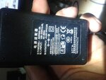
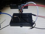
20161111_205042.jpg20161111_205107.jpg20161111_205201.jpg20161111_205231.jpg20161111_213702.jpg

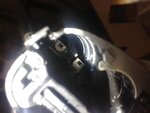
I tried to wiring 2 AA battery to battery like structre, but I couldn't open it. I have checked negative and positive terminals lot of time. So it shows that probably problem is related to terminal of structure. I need your helps, Is it possible that these roves which are ring like metal are not able to flow enough current for running of camera ?
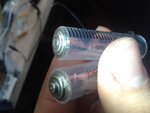
 

Good job fabricating a battery shell!

This is only a maybe... Can you be certain that your battery shell makes contact with the clips inside the camera? Your battery shell has wires which appear to be off-center. My camera has tiny contacts. I suspect they would not touch the wires on your battery shell.

As a possibility... Can you set your camera so it uses less power as you turn it on? Often I need to set my digital camera to a different mode than picture/video shooting, when I power up from borderline batteries. I need a mode that draws less power. On the other hand it draws more power when I start up to shoot pictures/movies, because a motor runs, extending the lens barrel and opening the lens. I don't know how many Amperes it draws, but I've had it shut down in mid startup, due to borderline batteries.

Your power supply might be adequate for your camera at 3A. You could easily find out with an oscilloscope whether its voltage drops at powerup.
 
  • Like
Reactions: jeolex

    jeolex

    Points: 2
    Helpful Answer Positive Rating
I had also a doubt about terminal of shell is contact to clips or not. I will be ensure its contact. Probably I will change terminals, maybe I might use brass to contact with clips, isn't it more suitable? I couldn't yet evaluate that my power supply enough or not, because first I have to ensure contact of terminals.

Thanks for your ideas
 

Another possibility... I believe you need to shape the positive end of your battery shell, so it is identical to a real battery. My camera has a barrier, or standoff, or wall, molded around its + contact. This prevents reverse battery polarity. The positive end of a battery has a protruding button shape, which fits the cavity, therefore it touches the + contact.

The negative end of a battery is broad and flat, so it cannot touch the + contact. Looking at your photograph, both ends of your battery shell appear to be broad and flat.
 
  • Like
Reactions: jeolex

    jeolex

    Points: 2
    Helpful Answer Positive Rating
Hi,

If the copper wires aren't soldered to the metal rings, you will go crazy with bad contacts, cold welding with pliers may help, but nothing beats a soldered connection.

If that isn't the problem, nor is the dummy battery not making contact with the camera terminals, nor the metal rings having some coating, you could get some 1 to 1.5mm rigid, solid copper wire (not coated with any enamel, it has to be bare copper), and try replacing the metal rings with a home-made spring/spiral of the copper, like the ones made of metal in battery powered equipment.
 
  • Like
Reactions: jeolex

    jeolex

    Points: 2
    Helpful Answer Positive Rating
Another possibility... I believe you need to shape the positive end of your battery shell, so it is identical to a real battery. My camera has a barrier, or standoff, or wall, molded around its + contact. This prevents reverse battery polarity. The positive end of a battery has a protruding button shape, which fits the cavity, therefore it touches the + contact.

The negative end of a battery is broad and flat, so it cannot touch the + contact. Looking at your photograph, both ends of your battery shell appear to be broad and flat.

I checked it again, and your are right, there is a barrier on positive side. Probably that is why the camera can't run. Positive side cannot touch to shell terminal. I will fix it tomorrow and try it again.

- - - Updated - - -

Hi,

If the copper wires aren't soldered to the metal rings, you will go crazy with bad contacts, cold welding with pliers may help, but nothing beats a soldered connection.

If that isn't the problem, nor is the dummy battery not making contact with the camera terminals, nor the metal rings having some coating, you could get some 1 to 1.5mm rigid, solid copper wire (not coated with any enamel, it has to be bare copper), and try replacing the metal rings with a home-made spring/spiral of the copper, like the ones made of metal in battery powered equipment.

First I will try to readjust positive terminal of shell. If I can't get any results, I will try to solder copper and this ring for better connection.

Thanks
 

I have done more suitable battery shell as used to AA battery terminals. I got good contact and saw warning that change battery. Probably next problem is the regulator circuit. I shared my last battery shell and regulator circuit.

20161112_131929.jpgBaşlıksız-1.jpg

I used LM338 which has 1.2-32V and 5A output range. And my power supply has 5V and 3A output. How can I supply energy of camera with these items.
 

I have also tried 5v 12A computer power supply with this circuit. I couldn't run it and got "change batteries" text, but this time I can look pictures what I take before. So It is almost certain that LM338 and circuit is not enough for my camera. Do you suggest MOSFET for this job ?

- - - Updated - - -

I tried MOSFET (IRLZ34N) that I used it before for my led bulb, but I couldn't run even the menu. In my circuit I have used jumper cables. Is it possible that the jumper cables couldn't flow high current that need for camera?
 

I have also tried 5v 12A computer power supply with this circuit. I couldn't run it and got "change batteries" text

It is normal for regulator IC's to drop 2 or 3V. Therefore you probably need to feed it a minimum of 6V, to get output of 3V.

In my circuit I have used jumper cables. Is it possible that the jumper cables couldn't flow high current that need for camera?

Your wiring appears sufficient to carry a couple of Amperes. However one faulty joint is all it takes to defeat your purpose. A joint of 1/3 ohm, carrying 3A, drops 1V. This can prevent your camera from operating.

Ideally you want to take a voltage reading inside the camera, although that is difficult. Instead try attaching a heavy load (3-6 A) to your battery shell, then take voltage readings at the load. Do you get your desired voltage (3.15V)?

At the IC output, install a large capacitor. 3300 or 4700 uF could be adequate. The capacitor helps to fill in momentary droops in the supply voltage.

You may get success simply by increasing the supply voltage. Did you select the 330 & 470 resistor values by experimentation? Try changing one or both values. Of course you don't want the camera to be exposed to a greater level than 3.15 V. That is the voltage produced by new batteries.
 
  • Like
Reactions: jeolex

    jeolex

    Points: 2
    Helpful Answer Positive Rating
Do you get your desired voltage (3.15V)?
Actually I have gotten 3.15V with LM338 circuit. There is no problem about Voltage supply, probably current amount could not enough for running camera.

At the IC output, install a large capacitor. 3300 or 4700 uF could be adequate. The capacitor helps to fill in momentary droops in the supply voltage.

I am not good in basic electronics. I started to electronic with arduino and learn it day by day. So I don't know exactly what is duty of capacitor. I just predict that It will store current and then give enough amperage to camera for running. Am I right ?
Did you select the 330 & 470 resistor values by experimentation?

I found all of them from internet what I tried, and made readjustment for my job. So I can get 3.15 V from LM338 regulator circuit and will try big capacitor (6800 uF) for guaranteed the running of camera.

- - - Updated - - -

I tried to place 6800uF capacitor between Vout and GND. I couldn't run it again, just opened my album and can looking to photos. :S
 

  • Like
Reactions: jeolex

    jeolex

    Points: 2
    Helpful Answer Positive Rating
I guess the problem is dropout voltage related, it looks like you need at least 5.7 V going into the LM338 for it to provide 3.15V + 3A out...

Thank you for your advice, but I tried to 12V 4.2A power supply with lm338, 3.15V ouput didn't run camera again. Am I have to use power transistor ?
 

So I don't know exactly what is duty of capacitor. I just predict that It will store current and then give enough amperage to camera for running. Am I right ?

Yes, that's the idea. Batteries can deliver a lot of energy instantly. Even AA size can provide several Amperes.

Digital cameras tend to go through batteries quickly (especially if you use the flash).

I tried to place 6800uF capacitor between Vout and GND. I couldn't run it again, just opened my album and can looking to photos. :S

Sometimes it is the same with my camera, when the batteries are weak. Then, after I successfully start up in that mode, it is easier for the batteries to step up to the mode for shooting pictures.

Now that you have succeeded in getting power to your camera, you need to try every trick in the book, so you can deliver several Amperes at a moment's notice.

Your power supply may have sufficient current reserve, but it is possible the wires need to be larger diameter. For all we know, the camera draws sudden 10A bursts of current, resulting in voltage drops. You should make your wires as short as possible. As a reasonable estimate suppose it is 2 feet round trip.
* If we specify a drop of 0.1V at 10A, then resistance can be no greater than .01 ohm. This is 2 feet of 17 AWG wire.
* If we specify a drop of .05V at 10A, then we want resistance of .005 ohm. This is 2 feet of 14 gauge wire.
This is not counting losses due to resistance in joints, tarnished contacts, etc. It will take some effort for you to reduce all losses, so that the camera gets stable voltage.

To clean contacts, use razor blade, sharpening stone, steel wool, etc.

Links to charts of wire gauges showing resistance and ampacity.

http://amasci.com/tesla/wire1.html

http://technifest.com/technical-documents/wire-guage/

http://www.powerstream.com/Wire_Size.htm
 
  • Like
Reactions: jeolex

    jeolex

    Points: 2
    Helpful Answer Positive Rating
Now that you have succeeded in getting power to your camera, you need to try every trick in the book, so you can deliver several Amperes at a moment's notice.

I found ACK800 ac adapter kit that is suitable for my camera. It is 3.15 V 2A. So I think 2A supplier will be enough for me.
I think about using power transistor as amplifier in order to get high current.

Link about high current voltage regulator with LM317: http://www.reuk.co.uk/wordpress/electric-circuit/lm317-adjustable-power-supply/

These diagrams maybe solve my problem. But before this hypothesis, I will try to increase cable diameter (I used jumper cables and alligator cables) and clean terminals for good contact.
 

I think about using power transistor as amplifier in order to get high current.

Link about high current voltage regulator with LM317: http://www.reuk.co.uk/wordpress/electric-circuit/lm317-adjustable-power-supply/

The article talks about installing a pass transistor. This is an effective way to increase current. You may need to adjust resistor values, in order to increase bias on the NPN transistor.

It's best if you make sure to supply the camera with 3V. Let me relate my own experience years ago...
I started to make an external supply for my (previous) digital camera. I was curious to see whether it would turn on at a lower voltage than its spec supply, so I applied less than 3V. Apparently this changed characteristics inside the camera, because after that time it seemed to need freshly charged batteries to make it turn on. Gradually this condition worsened until the camera refused to turn on at all. New batteries didn't help.

We can't be sure whether your camera will be harmed by sub-normal voltage. It's wise that you are designing your supply to deliver more than 3V. Parasitic resistance can reduce this value. If possible you should monitor voltage at the internal battery contacts.
 
  • Like
Reactions: jeolex

    jeolex

    Points: 2
    Helpful Answer Positive Rating
Dear friends,

Thanks for all of your ideas, advice, knowledge and efforts. I have solved my problem as following:

First I have almost abandoned my hope about this topic. I researched power transistors, capacitors, regulators... and thought about that why I don't use prepared circuit for LM338. I wanted to leave from all negative possibilities. And have done what I mentioned at below.

5a-adjustable-power-supply-circuit-lm338.gif devre.jpg

Left side what I found from internet, right side that I change some parts according to my items. And I used stripboard and 1mm copper wire for connections between components. Therefore I neglected inability of wiring that flow current averagely.


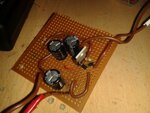
20161113_135157.jpg20161113_142515.jpg20161113_142530.jpg

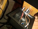
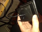
You can see the circuit and I put it to inside of plastic box as you see from pictures. As my mentioned in the beginning of my reply, I combined all of your advice. I also clean terminals of the shell for good contact to clips and ready for test.

20161113_154231.jpg20161113_154255.jpg20161113_154303.jpg

I tested it and got good results. There were no problem about running camera and charging flash. Again thanks for your helps. This forum site is one of my best :). And I have also recorded a video as my proof :)


In after days, I wanna record a video that how to make a main adapter for canon powershot SX150 :)

Best regards.
 

A little belated thought:

I think the problem is that the dynamic internal resistance of your PSU is too much (for example because the wires).

My advice:

Place a 100uF tantalum capacitor as close as possible to the output terminals of your PSU, ie as close as possible to the camera's input terminals.

Knowledge is knowledge. Late or earlier doesn t matter friend. So you are right. Probably problem was resistance of cables, terminals so circuit. I was removed to electrolytic capacitor which is placed input, and it was still running the camera. But I placed again capacitor due to need balance in current and voltage.

Thank you.
 

Status
Not open for further replies.

Similar threads

Part and Inventory Search

Welcome to EDABoard.com

Sponsor

Back
Top