Continue to Site

Welcome to EDAboard.com

Welcome to our site! EDAboard.com is an international Electronics Discussion Forum focused on EDA software, circuits, schematics, books, theory, papers, asic, pld, 8051, DSP, Network, RF, Analog Design, PCB, Service Manuals... and a whole lot more! To participate you need to register. Registration is free. Click here to register now.

Practical working of an L network matching circuit

Status
Not open for further replies.

himanshul

Newbie level 5
Joined
Jun 21, 2011
Messages
9
Helped
0
Reputation
0
Reaction score
0
Trophy points
1,281
Activity points
1,395
Hi friends,

I went through this extremely helpful and informative thread.... post 3.... and knew about the physical significance of imaginary part of the impedance.
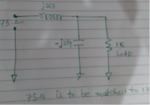
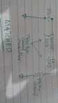
Here I am presenting a circuit which is an L network used for matching.On simplifying the circuit the equivalent circuit is shown below.
Now the text says that in the equivalent circuit the imaginary part of the impedance of inductor and capacitor cancels each and the circuit is matched.

Now I am not able to physically visualize both the imaginary impedance cancelling each other.
Can someone explain it in reference to post 3....

source of article...https://www.youtube.com/watch?v=AmwgtCH5fSc
thread url...https://www.edaboard.com/threads/27689/

regards
 

Attachments

  • new pic.png
    new pic.png
    220.4 KB · Views: 68
  • IMG_20161111_174845 (1).jpg
    IMG_20161111_174845 (1).jpg
    439.5 KB · Views: 73

You have to convert the 1k || -j284 circuit to an equivalent series circuit by applying basic complex arithmetic. (Convert impedance to admittance, add it, convert back to impedance).
 

I know about the calculations as I watched the video..but what I want to ask is why or how do the imaginary parts of impedance of inductor as well as capacitor cancels each other..... ??
 

Not sure if I understand the question correctly. Are you asking about cancellation of positive and negative reactances in general, or specifically for the impedance transformation circuit?

It's simple mathematics, isn't it? You can also sketch phasors if you prefer a more visual method. https://en.wikipedia.org/wiki/Phasor
 

LC series...
Phase change plays a part.
The inductor causes phase change to frequencies higher than its LR rolloff frequency.
The capacitor causes phase change in the opposite direction. The change is to frequencies lower than its RC rolloff frequency.
The result is to attenuate all frequencies, except that the resonant frequency is attenuated least. Bandwidth might be wide or narrow, depending on L:C ratio, and depending on ohmic resistance in the loop.

At resonant frequency the LC presents its lowest impedance. It may create 'springy action' back and forth, if the source is low impedance. If Q is very high the result can be to boost amplitude of the resonant frequency.
 

Status
Not open for further replies.

Part and Inventory Search

Welcome to EDABoard.com

Sponsor

Back
Top