Continue to Site

Welcome to EDAboard.com

Welcome to our site! EDAboard.com is an international Electronics Discussion Forum focused on EDA software, circuits, schematics, books, theory, papers, asic, pld, 8051, DSP, Network, RF, Analog Design, PCB, Service Manuals... and a whole lot more! To participate you need to register. Registration is free. Click here to register now.

LM331 Circuit not working

Status
Not open for further replies.
Hi,

Any advice?

Yes: Show us your schematic with all the voltages and inputs.

Usually you can rely on the circuits given in the datasheets. So - sorry for this - I assume there is an issue in your circuit.

Klaus

***
I underlined "your", because with many threads here the people say "I used the circuit like given in the datasheet", but when we finally see the true circuit ... there are differences (by accident or not).
 

I second Klaus' request.
Include all actual component values. Mention what supply voltages are being used.
If you include voltage readings and/or waveforms at some key test points, that would also help.
 

If the schematic has been followed, I would guess the problem is a lack of voltage at the output pull-up resistor.

The point labeled "VLOGIC" is a voltage input and should be tied to the supply of the logic gate following the circuit. If you do not provide that voltage, the circuit will still work but be unable to produce any output signal.

Brian
 

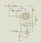
Ok I am attaching the image of my circuit drawn in proteus. It does not work there as well. LM331CKT.JPG

- - - Updated - - -

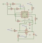
Ok I am attaching the image of my circuit drawn in proteus. It does not work there as well. LM331CKT.JPG. oops I Also included 2.2K resistor from pin 7 and diode in reverse mode.

- - - Updated - - -

Please ignore previous postings. See the attached image. Sorry for the inconvenience.lm331.JPG
 

Hi,

What about the rest of the requested informations?

Klaus
 

Hi KlausST,

I have marked all voltages as suggested. I checked for even U2 (not marked in JPG) it is +15V for pin 7 and -15V for pin 4.
 

Hi,

Now we have the same informations as in the datasheet.

To see what works and what not we need to see the output signals.
At least all the output signals of U1 and U2.

*****

Btw: You said the "real circuit" is not working. And it is no breadboard. Therefore I assume you have a PCB.
Do you have a schematic from your PCB tool? Because this schematic seems to be a Proteus schematic.
Or did you use Proteus to route the PCB.

In any case: the PCB layout could provide additional informations..

Klaus
 

Hi KlausST,
Proteus schematic is only representation for the design done on breadboard. The output from Pin No of 3 is +5v and output of U2 is zero.
 

Hi,

Proteus schematic is only representation for the design done on breadboard.

In post#2 I tried to explain, that we don´t need any schematic. Not this from the datasheet, not this from proteues.
It is very likely they are correct, therefore they are about useless for finding the issue.

What we need is the schematic of the circuit that does not work.

*****
If you made a PCB you should have the related schematic. Please post that schematic.

Also post a picture of your PCB.

The .... output of U2 is zero.

If there is an issue, then I expect U2_out to saturate to either supply rail.
But you say it is 0V.

--> check for an accidental connection to GND. Check for accidental short of the two C2 connections.

Klaus
 

Hi Klaus,

Kindly understand that I constructed schematic based on breadboard connection. If I show breadboard screen shot, it will be impossible to make out anything. If you have same circuit working in your lab, please share it. I have checked about everything, including rewiring half a dozen times. Fig.14 works just straight (stand alone V/F, without hiccups).
 

Hi,

We can help only if we have enough usefull information.

Klaus
 

You have to divide and conquer a circuit. You already know that the LM311 is working. Now test the opamp integrator on its own, and check out its proper operation

and output of U2 is zero.

When you say zero, does that mean:

0.00000
+0.01
-0.05
Or what?

I find it impossible that an integrator circuit's output remains exactly at zero, even in an absence of an input.
The opamp's own offset voltage would make the output to crawl towards saturation unless it is periodically reset.

.
 

Status
Not open for further replies.

Similar threads

Part and Inventory Search

Welcome to EDABoard.com

Sponsor

Back
Top