borna.barisic
Newbie
Hello, my name is Borna Barisic and i am from Croatia. If you don't mind i have a question about Raspberry Pi's PWM.
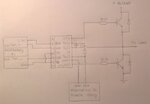
I have build a DC step down Buck converter with half H bridge and i am using IR2113 driver.
Schematics for that circle shown in (DC Buck schematic attachment).
I have watched PWM lessons for Raspberry Pi and thanks to them i managed to make a program in Python to generate two PWM signals from Raspberry Pi, but i cant make those PWM signal out of phase.
If i am right, for example, if i put frequency f = 1 Hz that means that time of whole period is T = 1 sec, time half of period is t=0.5 sec. In python program i used a time.sleep(t) function in while loop so when one of PWM signal (in this case buck_PWM_H,representing high signal) already starts, second PWM (buck_PWM_L,representing low sigal) waits for half a period and then starts. Then i would get two signals that would be out of phase (when "H" is 1 "L" is 0).
Well to be honest it did not worked that way.
Just to say regardless of time or frequency those two PWM signals were always in phase.
After that said i was wondering if you could help me by telling me how to generate (with Python code) two complementary PWM signals. I hope that i made myself clear enough for you to understand me. I am sorry for my grammar mistakes.
I will show you my Python code.
Best regards from Croatia and keep up the good job.
I have build a DC step down Buck converter with half H bridge and i am using IR2113 driver.
Schematics for that circle shown in (DC Buck schematic attachment).
I have watched PWM lessons for Raspberry Pi and thanks to them i managed to make a program in Python to generate two PWM signals from Raspberry Pi, but i cant make those PWM signal out of phase.
If i am right, for example, if i put frequency f = 1 Hz that means that time of whole period is T = 1 sec, time half of period is t=0.5 sec. In python program i used a time.sleep(t) function in while loop so when one of PWM signal (in this case buck_PWM_H,representing high signal) already starts, second PWM (buck_PWM_L,representing low sigal) waits for half a period and then starts. Then i would get two signals that would be out of phase (when "H" is 1 "L" is 0).
Well to be honest it did not worked that way.
Just to say regardless of time or frequency those two PWM signals were always in phase.
After that said i was wondering if you could help me by telling me how to generate (with Python code) two complementary PWM signals. I hope that i made myself clear enough for you to understand me. I am sorry for my grammar mistakes.
I will show you my Python code.
Code Python - [expand]
Best regards from Croatia and keep up the good job.
Attachments
Last edited by a moderator: