Continue to Site

Welcome to EDAboard.com

Welcome to our site! EDAboard.com is an international Electronics Discussion Forum focused on EDA software, circuits, schematics, books, theory, papers, asic, pld, 8051, DSP, Network, RF, Analog Design, PCB, Service Manuals... and a whole lot more! To participate you need to register. Registration is free. Click here to register now.

[moved] Need help -electronic circuit - microcontroller turning on 24V loads

Status
Not open for further replies.

bluehawkmlt

Newbie level 3
Joined
Nov 4, 2016
Messages
3
Helped
0
Reputation
0
Reaction score
0
Trophy points
1
Activity points
40
Hello there engineers! Who can help me with this circuit please? I am designing a circuit to control a load with two MOSFETs through two pins of my micro controller at the same time. (Please refer to the link provided, I will be using a different load instead of a motor). One must control the upper part of the load which in this case is the 24 Volt and one must control the GND of the load which is the lower case. In the lower case as you can see I already have an IRF540 which is an N Channel MOSFET. Now I only need to know how I can connect a MOSFET (I think it must be a P Channel) to the upper part of the load. I need this setup as I only have a limited amount of space on the PCB and want to increase the availability of the outputs. In example I need 4 MOSFETS on the upper part and 4 MOSFETS on the lower part of the load in which this will conclude to have 16 loads or outputs.

Thanks very much to whom can help me!!!

https://obrazki.elektroda.pl/9854968400_1478282754.jpg
 

Hi,

there is a high side switch (switching the +24V)
and there is a low side switch (switching the GND)

If you combine both then it is called half_bridge.

Two half_bridges build a full_bridge.

All these circuits are available ready to buy. This maybe is the most compact and easiest way for you.

To select those circuits you need to know:
* switching current (peak and continous)
* frequency
* duty cycle
* maximum allowed power loss (or voltage drop)

I recommend to do a search on the underlined items. Read about their theory, function, benefits, drawbacks...

Then come back with dedicated questions. Tell us your decisions and please post a drawing of your circuit.


Klaus
 
Thanks for your very fast reply KlausST!

I am designing a fireworks firing system and I think the most important thing is the switching current. I will be using a 24V DC supply. Each igniter or fuse is rated at 0.5A to burn and the max amount of time the MOSFETs must stay on is at 50ms. The max draw rate that I will have on each load is at 10A.

I will do my research and will post a drawing of my circuit when I will get it ready.

Thanks
 

I finally designed the circuit. The output will have a fireworks electronic igniter which used around 0.5A to fire and the maximum parallel connected igniters on the output will be 10.

I designed the circuit using logic level MOSFETs. The upper part is controlled with a Logic Level P channel MOSFET and the lower part is controlled with a Logic Level N channel MOSFET. The 3.3V supply will provide current for continuity testing of the connected igniters which will give an input to an analogue Multiplexer (Which still needs to be researched and if always it is possible).

Questions that I would like to ask:

(1) What can I do to remove the floating gate on the P channel till when the microcontroller switches on and outputs a 5V to maintain the P channel MOSFET switched off? I know that I must add a resistor but the microcontroller will be driving directly the gate and if I connect a resistor with the 24V, it won't be an ideal choice as far as I know!

(2) The 24V is used to fire the igniters, will it affect the analogue multiplexer?

(3) What analogue multiplexer can I use?
Untitled.png
 

Hi,

The P channel can't be driven from a 5V microcontroller pin.
You need additional circuit to drive the gate.

To prevent the gate from floating one usually connects a resistor between gate and source.

Klaus
 
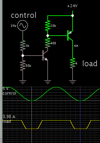
Typical circuit so that 0-5V can control operation of a P-device.

8555028200_1478661075.png


The high ohm resistors connected to supply rails are a necessary safety feature. They cause the transistors to turn off fully. Then you can disconnect the control device, yet the transistors will not conduct.

- - - Updated - - -

Nevertheless you should run tests to find out what can cause false triggers. This is important because your schematic has mosfets, and mosfet gates are sensitive to ambient electrical noise (coming from of mains hum, vehicle ignition systems, etc.)

Example, touch your finger to the N-device bias wire. Watch to see if it turns on and off at 50-60 Hz. If so then reduce the high-ohm resistor values.
 
Hi,

Further to what Brad has mentioned... maybe not necessary, all the same it might be an idea to include Schmitt triggers in that set-up to avoid false triggering.

I think Daycounter have a simple 2 BJT Schmitt trigger schematic, or there are many available manufactured ICs to carry out the function.
 

Status
Not open for further replies.

Similar threads

Part and Inventory Search

Welcome to EDABoard.com

Sponsor

Back
Top