eengr
Member level 4
Hi there
I am currently working on a design of a product. The product will take inputs from a remote sensor and log them on board. It has a micro-controller based circuit that will perform logging and other user interface functions.
The board has several inputs as 420mA input, sensors input (analog signals) , RS485 / USB interface etc. I have not included the full schematic here as it will make the whole message and picture size very big and the area I am concerned about is only a small portion of overall circuit.
The product is 24V DC (12V – 30V DC full range of input DC power) powered and has on-board voltage regulation to bring the voltage down to +5V & +3.3V Rails
The board will have terminal block (phoenix connector) type interface to outside world
https://www.phoenixcontact.com/online/portal/gb?uri=pxc-oc-itemdetail id=1840502&library=gben&pcck=P-11-02-11&tab=1
and whole assembly will be mounted in DIN rail type enclosure. This would mean that screw terminals on terminal blocks connections will be exposed to outside world with No mechanical cover around the screw terminals.
This product will go through EMC testing for compliance and the test I am concerned about is ESD. The standard required the Contact discharge to be +/- 6kV and Air discharge to be +/-8kV. This charge voltage will be applied directly to the screw terminals where the interface is done between the PCB of said product and the outside world.

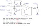
For one of the sensor interfaces I am using a differential amplifier circuit with LOW Pass filter at the input as shown in the attached picture. The inputs ‘SIG_POS’ and ‘SIG_NEG’ are connected directly to two points on screw terminal block. These points will be tested for ESD protection hence subjected to +/-6kV contact discharge & +/-8kV Air discharge.
The output ‘SIG’ is connected to ADC (for info only No questions on output side + there are rail decoupling caps on 5V rail of op-amp not shown in schematic). The analog signal coming in NOT very fast changing signal. So speed is not an issue. We sample it once every second
My question is that would this circuit be safe to handle the ESD test without damaging anything in the area shown in schematic OR would I need to add more OR different components. The ESD voltage level will be applied directly to the points marked as ‘SIG_POS’ & ‘SIG_NEG’. I have added the details of all the parts used next to schematic. My thinking was that the combination of R104 & R105 being 10K resistors & C102 & C104 of 10nF /50V caps would take the initial energy out of the ESD pulse and keep the rest of circuit safe. I don’t know what exact formulae to use to get the correct values for bringing the ESD level to safe levels using the Resistor/ Capacitor combination. Also I am not sure if using small 0402 packages would be good enough OR should I be using bigger footprint packages. Any expert help would be greatly appreciated as I want to fix these issues at this stage of the design instead of taking it to EMC test lab and then finding out that practically these components should have been different size or values.
I am currently working on a design of a product. The product will take inputs from a remote sensor and log them on board. It has a micro-controller based circuit that will perform logging and other user interface functions.
The board has several inputs as 420mA input, sensors input (analog signals) , RS485 / USB interface etc. I have not included the full schematic here as it will make the whole message and picture size very big and the area I am concerned about is only a small portion of overall circuit.
The product is 24V DC (12V – 30V DC full range of input DC power) powered and has on-board voltage regulation to bring the voltage down to +5V & +3.3V Rails
The board will have terminal block (phoenix connector) type interface to outside world
https://www.phoenixcontact.com/online/portal/gb?uri=pxc-oc-itemdetail
id=1840502&library=gben&pcck=P-11-02-11&tab=1and whole assembly will be mounted in DIN rail type enclosure. This would mean that screw terminals on terminal blocks connections will be exposed to outside world with No mechanical cover around the screw terminals.
This product will go through EMC testing for compliance and the test I am concerned about is ESD. The standard required the Contact discharge to be +/- 6kV and Air discharge to be +/-8kV. This charge voltage will be applied directly to the screw terminals where the interface is done between the PCB of said product and the outside world.
For one of the sensor interfaces I am using a differential amplifier circuit with LOW Pass filter at the input as shown in the attached picture. The inputs ‘SIG_POS’ and ‘SIG_NEG’ are connected directly to two points on screw terminal block. These points will be tested for ESD protection hence subjected to +/-6kV contact discharge & +/-8kV Air discharge.
The output ‘SIG’ is connected to ADC (for info only No questions on output side + there are rail decoupling caps on 5V rail of op-amp not shown in schematic). The analog signal coming in NOT very fast changing signal. So speed is not an issue. We sample it once every second
My question is that would this circuit be safe to handle the ESD test without damaging anything in the area shown in schematic OR would I need to add more OR different components. The ESD voltage level will be applied directly to the points marked as ‘SIG_POS’ & ‘SIG_NEG’. I have added the details of all the parts used next to schematic. My thinking was that the combination of R104 & R105 being 10K resistors & C102 & C104 of 10nF /50V caps would take the initial energy out of the ESD pulse and keep the rest of circuit safe. I don’t know what exact formulae to use to get the correct values for bringing the ESD level to safe levels using the Resistor/ Capacitor combination. Also I am not sure if using small 0402 packages would be good enough OR should I be using bigger footprint packages. Any expert help would be greatly appreciated as I want to fix these issues at this stage of the design instead of taking it to EMC test lab and then finding out that practically these components should have been different size or values.