tinystorm
Newbie level 6
- Joined
- Feb 18, 2015
- Messages
- 14
- Helped
- 0
- Reputation
- 0
- Reaction score
- 0
- Trophy points
- 1
- Location
- A concrete cave
- Activity points
- 137
Hello n good day edaboard veterans,
i have many questions to ask to verify my curiosity into something i have been trying to play around in simulators, questions in other forums, etc etc, on low noise amplifier designing. (example this 1
https://www.eevblog.com/forum/metrology/characterising-low-frequency-noise/
and this most recent very interesting thread
https://www.eevblog.com/forum/metrology/ultra-low-noise-reference-2dw232-2dw233-2dw23x/100/)
in those threads, and other many PDF in the google jungle, i can understand that in the LNA, opamp is just to gain up the noise, using LPF + HPF as bandpass, then measure the amplified noise output. some have designed it as x1000 gain, some x2000, x10000, etc. i took some time to create simulations to try them, i have never made any active filters before using opamp. i want to understand more about the opamp criteria, i dont quite understand it. (here comes all the questions)
1) in intersil application note 1560. a wideband LNA, they use HA5147 opamp. it has 0.09uVpp input noise. in the application circuit, it has a gain of x101, does the output in theory carry forth the input noise as approximately 9uVpp?
2) with the above in mind, i can understand that they choose HA5147 due to its high bandwidth. however in theory, are these the main criteria to look for [1] low Vpp noise? [2] bandwidth? [3] input/output impedance matching? <-- i have no clue how to do this [3].
3) in design of the LPF and HPF, if say 0.01Hz to 10Hz, i have read some use 1st order, some use 2nd order, etc. i assume the ideal is nearly brickwall? so in practical we should design 4th order LPF/HPF? but in many discussions i have seen, many are done with up to 2nd order, i am assuming this is to simplify design yes?
4) by combining my bits and pieces of knowledge, i came up with this (simulation)
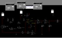
i inject 0.01Hz or 10Hz, and adjust the LPF/HPF so that the various measuring points show a -3dB drop, this give me the impression that the components are right to give a combined bandpass of 0.01-10Hz (2nd order)? is this the right way to design filter? for opamp i use OPA140 due to very low Vos/Ibias/noise, however, i assume this 1 is a very high input impedance opamp, i am not sure if i have matched the gain and input/output impedance in a right way. i seek the knowledge to know more about this, if anybody could enlighten me, thank you in advance.
using the above circuit as example, could i be right by choosing OPA140? @ 0.25uVpp noise? or due to the high gain x10000, should i forego low Ibias/Vos and go for primarily low noise density like AD4528/AD797/AD8428?
if to use AD797, due ot extremely high ibias, should the design focus then be to balance the input resistors so that the current noise will cancel each other? (im not sure if i understand rightly, but i assume is to equalize values of approx R2 and R3? i am not sure which "segment of resistance" to balance)
... and thank you all so much for reading such a long noob post
i have many questions to ask to verify my curiosity into something i have been trying to play around in simulators, questions in other forums, etc etc, on low noise amplifier designing. (example this 1
https://www.eevblog.com/forum/metrology/characterising-low-frequency-noise/
and this most recent very interesting thread
https://www.eevblog.com/forum/metrology/ultra-low-noise-reference-2dw232-2dw233-2dw23x/100/)
in those threads, and other many PDF in the google jungle, i can understand that in the LNA, opamp is just to gain up the noise, using LPF + HPF as bandpass, then measure the amplified noise output. some have designed it as x1000 gain, some x2000, x10000, etc. i took some time to create simulations to try them, i have never made any active filters before using opamp. i want to understand more about the opamp criteria, i dont quite understand it. (here comes all the questions)
1) in intersil application note 1560. a wideband LNA, they use HA5147 opamp. it has 0.09uVpp input noise. in the application circuit, it has a gain of x101, does the output in theory carry forth the input noise as approximately 9uVpp?
2) with the above in mind, i can understand that they choose HA5147 due to its high bandwidth. however in theory, are these the main criteria to look for [1] low Vpp noise? [2] bandwidth? [3] input/output impedance matching? <-- i have no clue how to do this [3].
3) in design of the LPF and HPF, if say 0.01Hz to 10Hz, i have read some use 1st order, some use 2nd order, etc. i assume the ideal is nearly brickwall? so in practical we should design 4th order LPF/HPF? but in many discussions i have seen, many are done with up to 2nd order, i am assuming this is to simplify design yes?
4) by combining my bits and pieces of knowledge, i came up with this (simulation)
i inject 0.01Hz or 10Hz, and adjust the LPF/HPF so that the various measuring points show a -3dB drop, this give me the impression that the components are right to give a combined bandpass of 0.01-10Hz (2nd order)? is this the right way to design filter? for opamp i use OPA140 due to very low Vos/Ibias/noise, however, i assume this 1 is a very high input impedance opamp, i am not sure if i have matched the gain and input/output impedance in a right way. i seek the knowledge to know more about this, if anybody could enlighten me, thank you in advance.
using the above circuit as example, could i be right by choosing OPA140? @ 0.25uVpp noise? or due to the high gain x10000, should i forego low Ibias/Vos and go for primarily low noise density like AD4528/AD797/AD8428?
if to use AD797, due ot extremely high ibias, should the design focus then be to balance the input resistors so that the current noise will cancel each other? (im not sure if i understand rightly, but i assume is to equalize values of approx R2 and R3? i am not sure which "segment of resistance" to balance)
... and thank you all so much for reading such a long noob post
Last edited by a moderator:


