Continue to Site

Welcome to EDAboard.com

Welcome to our site! EDAboard.com is an international Electronics Discussion Forum focused on EDA software, circuits, schematics, books, theory, papers, asic, pld, 8051, DSP, Network, RF, Analog Design, PCB, Service Manuals... and a whole lot more! To participate you need to register. Registration is free. Click here to register now.

adding and simulating audio amplifier IC. to proteus

Status
Not open for further replies.

Gaber Mohamed Boraey

Full Member level 2
Joined
Feb 26, 2015
Messages
149
Helped
4
Reputation
10
Reaction score
10
Trophy points
1,298
Activity points
2,246
hello everybody,

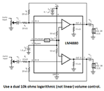
i am working on audio amplifier circuit, same as the audio amplifiers used at the headphones, but with different IC. of LM4840, with 2 channels output to be connected to two speakers,

i use Proteus for the simulation, but this IC. not included at the Proteus library, and i have added it, but when i simulate, it doesn't get connected to the other components and doesn't simulate the circuit.

so, do you know how after i add a component to the Proteus library, i be able to simulate the circuit with this added component?, or do you recommend any other design software which has such type of IC. and does simulate the circuits?

will appreciate your help,

Regards
 

Hi,

I can't help you with proteus...

But do you really need to simulate this amplifier?
If you keep on the datasheet it will work as expected. It is not a very critical curcuit.

On the other hand if you simulate it, but don't keep on the PCB recommendations, then the real circuit fails while simulation works.
So with this circuit I think you don't gain much from the simulation.

Klaus
 

okay, thanks for your answer, and i will look at the datasheet and make the circuit direct without simulation first, i just would like to simulate first, as the design softwares estimate the design alot to the real test, and if the circuit wouldn't work at real, i believe that it would need just some few changes with components and it should work, and for now, do you know another design software which does simulate electronic circuits and has bigger components libraries than Proteus?

Altium would be bigger library software?, or LT Spice?, what you recommend?
 

I have designed and built thousands of circuits using name-brand parts from reliable local distributors (not fakes or rejects from ebay) and all work perfectly. I used the spec's from datasheets. None were simulated first but later the simulations were done to show other people. People complain on these forums that their simulations do not work but the circuits work perfectly when they build them.
 

okay audioGuru, Great, i do it direct from the datasheet then, and let you know, thanks for your care to respond
 

hello,

i have decided this hi-fi headphone circuit, and i need your help or i ned to make sure about audio controlling at this the attached circuit, as you see it has no volume control, " there is no variable resistor at the circuit", also i would like to make one variable resistor to up/down the volume at both the speakers, so please where i can add this variable resistor at the circuit?
can it work if i added a VR as i made on the second image of the circuit of 20kohm?, i just need to make sure of this before i prototype the circuit

will apprecaite your response,
regards 1.png

hifi-headphone-amplifiercircuit.png
 

Is the circuitstoday website from a parallel universe where resistor values are specified in µF?

To be serious, the first circuit with removed 20k resistors will definitely not work. Placing a short for the 20k resistor sets a gain of zero, the pot with wiper connected to ground ruins the DC bias and neither works as a volume control. With some corrections, it could be a balance pot, for a stereo volume control you would need a stereo pot.
 

Hi,

I agree with FvM.

My comment about the schematic:
The most reliable source of a standard schematic is the datasheet.
Reading and understanding of the datasheet is essential. For newbies as well as for professionals.

There is so much wrong information in the internet ....

*****

You may use a pot as volume control:
--> do an internet search for "pot as volume control"
The pictures show you the circuit and the connections.
The documents give you a lot of related informations

You may use digitally controlled volume curcuit.
--> do an internet search for "digital volume control circuit"

Klaus
 

ok, thanks, for the stereo pot, where it should be connected at the circuit above, for controlling the volume at both speakers, it will be 3 terminals, so where it should be connected, as the circuit at the datasheet, and the website doesn't provide controlling the volume

for the digital volume control, i don't need this, i only need to add POT to this circuit, so where you recommend it to be connected?
 

so where it should be connected, as the circuit at the datasheet, and the website doesn't provide controlling the volume
Why not use a standard potentiometer circuit in front of the headphone amplifier? You could use a variable 20k resistor in the feedback path. But as the resistor carries some bias current, a pot in this place might cause scratching sounds when turned. Not recommended, I think. An audio pot should be always used with no DC voltage across it.
 

because i am building a headphone with new option, which does exist at this IC, and not at the standard circuit

- - - Updated - - -

i will try standard potentiometer circuit in front of this circuit, but can you please send me a link of potentionmeter circuit i can use with the above circuit?, or attach it here?, and what place exactly you mean in front of the headphone amplifier ?

you mean before the speakers?
 

Standard potentiometer circuit is amplifier input to wiper, CCW pin to ground, CW pin to signal source.
 

This headphones amplifier IC has a very low output power so speakers will make very faint sounds. A volume control is always used at the input of an amplifier and the volume control should have an audio logarithmic taper, not linear. Rf determines the gain of the amplifier.

Here is how volume controls are added:
 

Attachments

  • LM4880.png
    LM4880.png
    40.8 KB · Views: 199
  • Like
Reactions: FvM

    FvM

    Points: 2
    Helpful Answer Positive Rating
hello,

is there is a way to control the volume at this circuit by only one potentiometer?, for example, if i added a pre-amplifier circuity before this circuit with one volume potentioLM4880.pngmeter and dual audio out and connect these dual out to the input of this circuit, would it work?, or do you have any suggestions?

as i am using this circuit for headphone speaker, and doesn't make any sense to control each speaker with a separate volume button as shown at this circuit, so i need only one volume button to control both speakers sound

what you suggest?
regards
 

Hi,

There are no "two independent pots"

It is ONE DUAL pot = STEREO POT = two channels, but ONE knob

It´s all said before. Read posts again.

Klaus
 

Status
Not open for further replies.

Similar threads

Part and Inventory Search

Welcome to EDABoard.com

Sponsor

Back
Top