Continue to Site

Welcome to EDAboard.com

Welcome to our site! EDAboard.com is an international Electronics Discussion Forum focused on EDA software, circuits, schematics, books, theory, papers, asic, pld, 8051, DSP, Network, RF, Analog Design, PCB, Service Manuals... and a whole lot more! To participate you need to register. Registration is free. Click here to register now.

Drive Mosfet with 5V

Status
Not open for further replies.

gauravkothari23

Advanced Member level 2
Joined
Mar 21, 2015
Messages
640
Helped
5
Reputation
10
Reaction score
4
Trophy points
1,298
Activity points
6,922
Hi all,
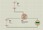
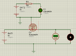
I have a small issue. how can i drive a IRLML6402 Mosfet with Source voltage of 9V and gate 5V.
i have tried a circuit in which i am using IRLML6402 Mosfet.
Source Voltage = 9v.
Gate Voltage = 5V.
But i am not getting any output at Drain Pin of mosfet.
 

hi,
The IRLML6402 is a P MOSFET, check the voltage polarities
E
 

Attachments

  • irlml6402.pdf
    171.1 KB · Views: 52

hi,
A P MOSFET requires negative voltages on the Gate and Drain with respect to the Source in order to control Source to Drain current conduction.

E
 

i have tried a basic circuit. but its not working.
but i am not getting any output at drain pin
circuit attached.

- - - Updated - - -

what changes are to be made to get a proper output of 9v
 

Attachments

  • IRLML6402.png
    IRLML6402.png
    26.5 KB · Views: 98

Hi,

Where is "B2 +" connected to?
You must not leave it unconnected.

Klaus
 

Hi,

Doesn't the voltmeter show 9V at the drain?
 

Hi,

Doesn't the voltmeter show 9V at the drain?

yes it shows in schematic, but it does not work in my circuit

@KlausSt.... i have a connected a LED to B2 but still the things are not working.
but when i connect the gate pin to 9v(-), the voltmeter shows 9V and then after when i keep the gate pin floating the voltage at drain pin is around 5V.
but when i connect the gate pin to 5V(+) or 5V(-), no action has been taken. the voltage does not changes.

- - - Updated - - -

but the same when i tried connecting the gate pin to 9V(+), then too the voltage shows 5v at drain pin.
atleast it should go to 0V when gate pin connected to 9V(+).
 

Try adding a load in parallel with the voltometer.
 

Hi,

then after when i keep the gate pin floating
Never let the gate floating.

i have a connected a LED to B2
B2 has two connections, you only show one.
A Led has two connections. How you connected it is unclear.
--> show the complete schematic wher we can see your ON setup and OFF setup.

Klaus
 

Hi,


Never let the gate floating.


B2 has two connections, you only show one.
A Led has two connections. How you connected it is unclear.
--> show the complete schematic wher we can see your ON setup and OFF setup.

Klaus

i am sorry for the small error from my side.
i have not connected the ground of both the batteries together.
but now i have done it. connected (-) of both 9V and 5V batteries together.
and the things are still not working perfect. i have 3 results
i have also connected a small DC motor in parallel to voltmeter.
when gate is connected to 5V(-) = drain output is 9V and DC motor gets ON
when gate is connected to 5V(+) = drain output again is 9V and DC motor gets ON
when gate is left floating = drain output is 5V
why i get drain output as 9V when gate connected to 5V(+).
Complete circuit diagram attached.
 

Attachments

  • IRLML6402-new.png
    IRLML6402-new.png
    35.9 KB · Views: 86

Complete circuit diagram attached.
Really? You have connected the gate to ground, Vgs = -9V, MOSFET permanently on.

If you want to further modify the schematic, please notice that Vgs has to be applied between gate and source. Source node is at input voltyage level (+9 V). To switch the MOSFET off, you'll apply Vgs < 0.5V respectively > 8.5 V relative to ground, to turn it on, Vgs > 2.5 V, respectively < 6.5 V relative to ground.

A 5V source referred to ground (e.g. a microcontroller IO pin) won't be able to switch the MOSFET off without a level shifter.

but when i connect the gate to 9V(+), then i get a output voltage at drain as 5V. and the same when i connect the gate to 5V(+) then it shows 5V and also when the gate pin is left floating, output voltage is also 5V, then why the mosfet get off only half. i mean output voltage drops from 9V to 5V when gate connected to (+) instead of droping the voltage from 9V to 0V.

- - - Updated - - -

Really? You have connected the gate to ground, Vgs = -9V, MOSFET permanently on.

If you want to further modify the schematic, please notice that Vgs has to be applied between gate and source. Source node is at input voltyage level (+9 V). To switch the MOSFET off, you'll apply Vgs < 0.5V respectively > 8.5 V relative to ground, to turn it on, Vgs > 2.5 V, respectively < 6.5 V relative to ground.

A 5V source referred to ground (e.g. a microcontroller IO pin) won't be able to switch the MOSFET off without a level shifter.

i even tried using this circuit...
but the problem is same..
why the voltage does not drops below 5v when gate is connected to (+).
 

Attachments

  • MOSFET_high_side_driver.png
    MOSFET_high_side_driver.png
    9.8 KB · Views: 141

why the voltage does not drops below 5v when gate is connected to (+).

Have you put a resistor from the gate to v+?

Also, why not try swapping the gate and drain, and maybe even throwing in the source, connections in the real circuit, methodical swapping/rotation of cables between pins may show human cabling error. Are you experimenting with the SOT-23 that appears in the Infineon (IR) datasheet? Are you sure you're connecting the gate to +9V and 0V? It's an easy mistake to make.
 

The circuit in post #13 is fine. If it doesn't work, your hardware implementation is wrong (defective parts, wiring errors, whatsoever).
 

Thanks you all...
things are working perfect.
i have tried using the circuit posted in the Post #13.

- - - Updated - - -

would like to ask one more thing related to this topic.
just for a knowledge. can i use this type of circuit with i have attached.
what is the difference between the circuit with i have attached and the circuit posted on post #13.
because i have tested both the circuits, both work fine. but don't know if the circuit attached is reliable to use or not.
 

Attachments

  • IRLML6402-new1.png
    IRLML6402-new1.png
    26.7 KB · Views: 95

Hi,

It doesn't work reliably.

I told you in post#10: Never let the gate floating.

But you don't care about this.

Klaus
 

Hi,

Post #13 circuit shows an NPN used as an inverter (high input = low output, low input = high output), like an open collector: when turned on it sinks/draws positive voltage away from the load (in that circuit the load is the MOSFET, followed by the motor). In the circuit, the resistor holds the PMOS gate high, when the NPN is turned on (high voltage into base), the positive voltage at the MOSFET gate via the resistor is pulled down through the NPN/pulled away from the PMOS gate.

Also, to think about things a bit, basically, typical for NPN is collector on V+ and emitter on 0V/V-; otherwise, as in the schematic in #16, one could consider it as doing nothing but having the base driven by a voltage, as the collector is on 0V, so where's the +V going to come from to hold the PMOS gate high when it should be off? Plus, it couldn't work as desired even with NPN collector on V+, like that, when the NPN were to be turned on, you'd be turning the PMOS off, a major difference. Compare circuit in #13: PMOS tied to V+ when not turned on; in #16, looks always like PMOS gate would be low to me, i.e. PMOS "on", except anything trickling from base to emitter when NPN is turned on.
 

Thanks, but as KlaussT said that, the gate pin should not be left floating but when....
when the NPN is turned on (high voltage into base), the positive voltage at the MOSFET gate via the resistor is pulled down through the NPN/pulled away from the PMOS gate(circuit = Post #13).
wont this thing make the gate pin float.
and in the case of (Circuit = post #16), if there is an only issue of not to keep the gate pin floating when NPN is off, we can use a pullup resistor between 9(+) and gate pin. is it not possible to do so..
dont get me wrong... the things are just for my knowledge, because i am bit confused in working of both the circuits.
 

The circuit in post #16 has many issues.
- missing pull-up (already mentioned)
- transistor polarity inverted
- missing gate current limiting resistor
- missing LED current limiting resistor

As shown, both transistor and LED will be burned, that's it.

Hard to say how it could be fixed, or to decide what's intended function and what's drawing fault.
 

Status
Not open for further replies.

Similar threads

Part and Inventory Search

Welcome to EDABoard.com

Sponsor

Back
Top