Continue to Site

Welcome to EDAboard.com

Welcome to our site! EDAboard.com is an international Electronics Discussion Forum focused on EDA software, circuits, schematics, books, theory, papers, asic, pld, 8051, DSP, Network, RF, Analog Design, PCB, Service Manuals... and a whole lot more! To participate you need to register. Registration is free. Click here to register now.

Pre-regulator circuit problem

Status
Not open for further replies.

S.Quoc.S

Newbie level 4
Joined
Nov 15, 2015
Messages
6
Helped
1
Reputation
2
Reaction score
1
Trophy points
1,283
Activity points
1,391
Hello everyone, I have a problem with my regulator for my bandgap circuit. The schematic is attached below. I add some PMOS diodes ( Drain shorted to Gate) in series with the R3 resistor to reduce the amount of resistance I need to put on the R3 resistor.
In my testbench, I use a ideal current source as reference current produced by bandgap core and I sweep the Vin voltage to measure the output Vpre-reg voltage. However, the output voltage increases linearly with the Vin voltage instead of being clamped to a fix value after the input voltage large enough :-?. I don't know what caused this issue. What do you think ?
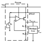
regulator.png
 

Hi,

I thought a regulator error amplifier needed a Vref on Vin+ and the feedback on Vin-, maybe I'm wrong for your design.

What's a bandgap core? Home-made or manufactured? I ask as it's nice to learn things, and discrete voltage references are something I like but know will never be any good, and you're an IC designer.

Would a resistor between the base and collector of Q4 and ground help?
 

Hi d123,

I'm not sure about the Vin- and Vin+ but follow the schematic above if the Vpre-reg is lower than the expected value, voltage drop on R4 will lower than the drop on the diode at Vin- that will make the opamp output will be lower, thus the Vsg of the PMOS will be higher and so the Vpre-reg will go up and the balance point will be met. I've already tried to swap Vin+ and Vin- but no help.

The bandgap core is the bandgap circuit, it generate Proportional To Absolute Temperature current ( Iptat) and transfer it to a PTAT voltage through a resistor, then sum this ptat Voltage with the Complementary To Absolute Temperature voltage ( Vctat). The result is the output voltage(Vout) that immune to temperature change. Hope you satisfied with this.

I've tried a resistor between the base and collector of Q4 but no help.
 
  • Like
Reactions: d123

    d123

    Points: 2
    Helpful Answer Positive Rating
Hi,

Thanks for explaining. I think I haven't understood circuit operation/a part of the description well, because I would have thought if the Op Amp output goes lower then the PMOS will turn on more (Vgs will fall, put differently, increasing "-Vgs")? I'm dimly guessing that something may be the wrong way round on that circuit. Would using an NMOS instead to compare response be of any use, or possibly better, powering Q4 from the supply rail or a current mirror/source?

I think I've understood the circuit now. That's hard to make, for some-one like myself: The BJT diode and bandgap need to pe powered from a known voltage, which can only come from the PMOs/EA set up to provide the EA with a known Vref? That's a hard circle to square.

Another guess...Does the Op Amp (or is it a comparator) need compensation?

Does the bandgap itself need a start-up circuit, or doesn't that apply to this design?

- - - Updated - - -

Hi again,

I know the schematic is probably far removed from your actual circuit, and simulation with first components found may not be very applicable to reality, but I had a go with this one on Tina-TI, and got 4.99V out for 5, 10 and 15Vin, if that's of any help. Apologies for the crossed wires coming off the current mirror.

(Hate to ask: Was your PMOS the wrong way round?)

On a breadboard with +-50ppm resistors and 2N2222As the Widlar Bandgap puts out an unreliable bad ppm/ºC 1.2V across temp, in the simulation I only got ~600mV.

PRE REGULATOR.JPG

Once again, thanks for explaining the circuit operation, I like things like that, and have learnt something new, thanks.
 
Last edited:

Status
Not open for further replies.

Part and Inventory Search

Welcome to EDABoard.com

Sponsor

Back
Top