Continue to Site

Welcome to EDAboard.com

Welcome to our site! EDAboard.com is an international Electronics Discussion Forum focused on EDA software, circuits, schematics, books, theory, papers, asic, pld, 8051, DSP, Network, RF, Analog Design, PCB, Service Manuals... and a whole lot more! To participate you need to register. Registration is free. Click here to register now.

Circuity to transform positive DAC output to negative voltage for FET gate biasing.

Status
Not open for further replies.

Terminator3

Advanced Member level 3
Joined
Feb 25, 2012
Messages
802
Helped
71
Reputation
142
Reaction score
63
Trophy points
1,308
Activity points
9,027
Please recommend me some options which could be used to realize this task:
Biasing signal 0..3.3v => convert => biasing signal 0..-4v (signal freq <100kHz)

Configuration:
1. DSP provides signal from the DAC output in the range 0..3.3v
2. I need to convert this output to 0..-4v range. I have -5V negative voltage supply.
DAC output signal frequency is at least 50kHz.

I need to provide varying negative biasing of FET transistors gate pin in range around 0..-4v.
I am using common source configuration, and source pin must be connected directly to ground plane using grounding VIAs (FET stability considerations) Negative voltage supply is the only way to provide biasing in this case, because source pin could not be biased above the ground. So my design is complicated by this requirement.
 

Additionally, look for a charge pump negative voltage generator. Like the ubiquitous ICL7660
 
I am aware of inverting amplifier, but some thing confuses me: Could an OpAmp be used as negative voltage load switch?
For example, there is a circuity:
**broken link removed**
three transistors are used. I want to design similar negative voltage load switch but with voltage tuning capability. One way is to use potentiometer (mechanical tuning) + above circuit. Could not the same thing be done using single transistor + OpAmp?
 

Hi,

what do you mean with "switch"?

A mechanical or analog switch is closed or open.
Do you need the negative bias voltage PLUS a switch?

With the DAC you can set the voltage to any desired value from x to y Volts. Isn´t this enough? (x and y can be adjusted with resistors)

Klaus
 

For MMICs the gate impedance is desired to be low-Z and low
noise. The op amp's high frequency output impedance may or
may not be suitable (but likely better than other options).

Element controller ICs might be found which perform both drain
switch and gate active bias control (although likely without a
port for you to apply a DAC signal). I've had occasion to design
three generations of such critters, but for a military customer
and no path to the commercial market.

How you set bias wants some thought. Setting the bias directly
by DAC probably means you want either a cal-map and some
telemetry (device temp, power sensor?) or a feedback point
such as a drain current sense resistor. What are you looking to
control, to what end? Might you really want the DAC to indicate
drain current (as sense resistor voltage drop) and let an op amp
close the loop, to that, instead of an open loop assertion of a
gate bias voltage (which lets drain current wander with gross
temperature and recent drive-level history)?
 

Hi,

what do you mean with "switch"?

A mechanical or analog switch is closed or open.
Do you need the negative bias voltage PLUS a switch?

With the DAC you can set the voltage to any desired value from x to y Volts. Isn´t this enough? (x and y can be adjusted with resistors)

Klaus
I just only need biasing. Previously i wanted to use switch with negative voltage output + pull-up to ground.
I am not sure i unterstand "x to y Volts", maybe you just gave me a very good idea:
Maybe I can use resisitive voltage divider between -3.3v and DAC output, for example R1=R2,
-3.3v and 3.3v from DAC will provide 0v.
-3.3v and 0v from DAC will provide -1.65v.
 

In case this can be adapted...
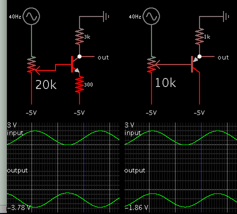
Send positive signal to bias a transistor operating from a negative supply.

4350223500_1477534585.png


The first circuit appears able to produce output down to -4V (in simulation). However notice that the output is in inverted phase from the input.

The second one (emitter follower) has output phase matching input phase. However output does not cover as wide a range as your spec. In fact you can get about the same result by using a potentiometer to pull your positive signal into the negative region.
 
Hi,

I'm really confused.
Please give a schematic or a picture of what you want to do.

I still think a simple inverting Opamp circuit should work. But I don't understand the "switching" and why you now talk about using a resistive voltage divider to -3V3...

Please clarify the function, and give your specifications in values so we calculate with. Voltages, expected precision...

Klaus
 

Maybe I can use resisitive voltage divider between -3.3v and DAC output, for example R1=R2,
-3.3v and 3.3v from DAC will provide 0v.
-3.3v and 0v from DAC will provide -1.65v.
Yes you can do that, but the solution doesn't meet the specifications of your original post which requires 0..-4V range. It also adds voltage error caused by the -3.3V supply. If your original specification has no significance, why would we think about it at all?

A perfect solution for the adjustable negative bias has been already given. Later you handed in a switch function.

The first obvious question is why the bias voltage can't be switched by toggling the DAC code between zero and set point? But if there's a requirement to switch the bias voltage independent of the DAC controlled voltage, this can be surely done.

Your load switch circuit example seems overdone at first sight because a bias voltage don't need to source a high current.

For clarification, you should specify the expected bias voltage load current, respectively acceptable maximum output impedance. And switching speed requirements, if any.
 
Status
Not open for further replies.

Part and Inventory Search

Welcome to EDABoard.com

Sponsor

Back
Top