exp
Full Member level 1
Hi,
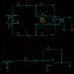
Consider the following two circuits, being an integrator with identical component values (R, C, OpAmp impedances, gain, ...) in its single-ended and fully differential version (the amplifier is a behavioral model basically just a VCVS):

Ignoring the nonlinear resistance in the circuit and I confirm with transient simulations that both give the same identical numerical results up to numerical precision.
However, then I add the simple nonlinear resistor (just a pvccs) described by
i = g1*v + g3*v^3
Note that there is no even order term! Now the fully differential circuit gives an error (compared to the linear version) that is exactly (up to numerical precision) a factor of 4 smaller than the single ended version.
This can't be coincidence. Why?
Consider the following two circuits, being an integrator with identical component values (R, C, OpAmp impedances, gain, ...) in its single-ended and fully differential version (the amplifier is a behavioral model basically just a VCVS):

Ignoring the nonlinear resistance in the circuit and I confirm with transient simulations that both give the same identical numerical results up to numerical precision.
However, then I add the simple nonlinear resistor (just a pvccs) described by
i = g1*v + g3*v^3
Note that there is no even order term! Now the fully differential circuit gives an error (compared to the linear version) that is exactly (up to numerical precision) a factor of 4 smaller than the single ended version.
This can't be coincidence. Why?