Continue to Site

Welcome to EDAboard.com

Welcome to our site! EDAboard.com is an international Electronics Discussion Forum focused on EDA software, circuits, schematics, books, theory, papers, asic, pld, 8051, DSP, Network, RF, Analog Design, PCB, Service Manuals... and a whole lot more! To participate you need to register. Registration is free. Click here to register now.

Low noise split supply converter sought

Status
Not open for further replies.

bnevins

Member level 1
Joined
Jul 25, 2015
Messages
34
Helped
1
Reputation
2
Reaction score
1
Trophy points
8
Activity points
263
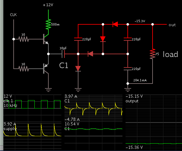
I want to go from +5V or +12V to +/-15V at 200mA. The noise/ripple
must be very low because it is a supply for a low noise amp.
The LT1533 has a nice demo board, but the push-pull transformer cannot be found and the Iout is a little low.,
https://www.linear.com/solutions/2506

I could use a module, but I cannot find one with comparable low noise/emi/ripple.

The solution need not be push-pull, but I do not know what else to use.
 

Use a dual output module with higher dc output voltages and follow that up with a pair of linear 15v regulators.
If you want really quiet, fit some passive LC filtering after the linear regulators to attenuate further any wideband noise.
 

The LT1533 should work fine from a 12V input, but its 1A current limit means 5V won't provide enough power. There are certainly many other off the shelf SMPS transformers you could use instead of the one in the reference design.

But it's likely not necessary to use a specialty part like the LT1533. A push pull converter with proper snubbers, layout, and output filters can have extremely low noise.
 
Use a dual output module with higher dc output voltages and follow that up with a pair of linear 15v regulators.
If you want really quiet, fit some passive LC filtering after the linear regulators to attenuate further any wideband noise.

Could you recommend specific parts or a product line? Everyone
I have tried had loads of EMI, so much I did not think an LC filter would work.
 

Everyone I have tried had loads of EMI, so much I did not think an LC filter would work.
LC filters and linear regulators are effective against conducted emissions, but radiated emissions are trickier. Reducing radiated EMI at the source with snubbers is helpful, and shielding the SMPS should take care of the rest.

What frequency range are you concerned about?
 

LC filters and linear regulators are effective against conducted emissions, but radiated emissions are trickier. Reducing radiated EMI at the source with snubbers is helpful, and shielding the SMPS should take care of the rest.

What frequency range are you concerned about?

100Hz to 10Mhz is the useful range of the amplifier.
If I use a module, I cannot put a snubber on the phase node.
Shielding might help a lot--can I experiment with a steel can?
 

I initially assumed this was for a low noise audio pre-amplifier.

At 10Mhz you are going to encounter stray coupling problems due to direct radiation from any switching power supply.
The physical layout and screening (and grounding) is going to be of vital importance just as important as the actual parts specified.

It might be a good idea to physically separate the voltage step up part of the circuit from the linear regulator and passive filtering part of the circuit.

The simple way is just to use a large battery and linear regulators to run the device, and recharge the battery when the device is not being used. Probably not practical, but its guaranteed to be very low noise.

Another possibility might be a small sine wave power oscillator with voltage step up transformer, rectifier and LC filter. There should be zero switching noise only some slight low frequency ac ripple, which a linear regulator should completely eliminate.

Any switching regulator is going to be problematic here.
If you can get around needing that somehow, it totally eliminates the basic source of the problem.
 

Consider a capacitor based voltage multiplier. No EMI, no transformer.

This simulation converts +12V to -15V 200mA.


C1 is a charge-pump capacitor. By adjusting its value, as well as by adjusting current through the transistors, you get a desired output voltage.

To increase 12V to 15V, use a similar arrangement, except with fewer stages and reversed diode orientations.
 

100Hz to 10Mhz is the useful range of the amplifier.
If I use a module, I cannot put a snubber on the phase node.
Shielding might help a lot--can I experiment with a steel can?
Sure, you can use PCB mount shields meant for RF applications, like this. But then the PCB ground plane acts as one side of the shield, so you will likely need a 4 layer PCB and good use of via fences.

My approach would be to have the boost converter with an additional LC filter on both the input and output, with all of that inside the shield. That should take care of all interference in the MHz range. Then a linear regulator outside the shield can take care of the lower frequency interference.

- - - Updated - - -

The simple way is just to use a large battery and linear regulators to run the device, and recharge the battery when the device is not being used. Probably not practical, but its guaranteed to be very low noise.
Using batteries is the absolute lowest noise option, if size and weight isn't a concern. And as you say, you do have to periodically charge the batteries, during which time you'll get EMI.
 

Consider a capacitor based voltage multiplier. No EMI, no transformer.

This simulation converts +12V to -15V 200mA.


C1 is a charge-pump capacitor. By adjusting its value, as well as by adjusting current through the transistors, you get a desired output voltage.

To increase 12V to 15V, use a similar arrangement, except with fewer stages and reversed diode orientations.

I will look into switch cap converters---I do not need a lot of power

- - - Updated - - -

Thanks for the shield tip. It can be a 4 layer board.
 

There's no reason switched capacitor supplies can't generate as much EMI as boost converters. If anything, they require higher peak currents than boost converters will.
 

There will be an auxiliary DC input (banana jacks?) so the user can use batteries or other DC sources.
So far main transformer to linear regs is the only approach proven to work.
 

There will be an auxiliary DC input (banana jacks?) so the user can use batteries or other DC sources.
So far main transformer to linear regs is the only approach proven to work.
Stick with sine waves and a transformer to step up voltage, and provide galvanic isolation as required. Anything that hard switches will generate harmonics that will be a problem.
 

Use a dual output module with higher dc output voltages and follow that up with a pair of linear 15v regulators.
If you want really quiet, fit some passive LC filtering after the linear regulators to attenuate further any wideband noise.

This provides quite a lot of bang for the buck. In this power range dual output supplies are like $5.

Adding an input LC, output LC and post regulators is also easy and gives a lot of bang for the buck.

I see batteries being mentioned so I'm not sure how critical power dissipation is but there is an advantage to choosing +/-15V rather than 12 and burning up the extra 3 volts with series R. At only 100mA you can throw 20 ohms or so of series R at the problem too. Nothing is better for filtering than R and at low power levels you can actually use it.
 

There's no reason switched capacitor supplies can't generate as much EMI as boost converters. If anything, they require higher peak currents than boost converters will.

Yes, advantages and disadvantages need to be taken into account with either method. The inductor radiates a magnetic flux field. Capacitors charge/discharge with abrupt current spikes.

To level out the spikes, I found it works to limit bias to the transistors, so they turn on partially (resistive drop). Then the waveforms are pulsed DC 800 mA (50% duty cycle). The supply provides 5W, and the load gets 3W (simulated). Efficiency 60 percent. Might be acceptable, might not be.

Another thing to consider is interleaving two of my schematic. It depends on how badly we want to avoid using inductors/transformers.
 

There's no reason switched capacitor supplies can't generate as much EMI as boost converters. If anything, they require higher peak currents than boost converters will.


That makes sense. There is no component inductor, but you still have rapidly changing voltages and the currents in the stray L of pcb traces and components. It would be interesting to see a quantitative comparison
between switched cap and push-pull at the same voltage and power levels.

- - - Updated - - -

Use a dual output module with higher dc output voltages and follow that up with a pair of linear 15v regulators.
If you want really quiet, fit some passive LC filtering after the linear regulators to attenuate further any wideband noise.

Can you give an example of a module that generates +/-18V from 12V? I could not find one.
You can get line to +18V (CUI corp) and use them in parallel to get +/-18V. However, there was loads of emi.

- - - Updated - - -

Stick with sine waves and a transformer to step up voltage, and provide galvanic isolation as required. Anything that hard switches will generate harmonics that will be a problem.

Where would I get a transformer, and what would it be called? "Audio power transformer" ?
 

That makes sense. There is no component inductor, but you still have rapidly changing voltages and the currents in the stray L of pcb traces and components. It would be interesting to see a quantitative comparison
between switched cap and push-pull at the same voltage and power levels.
Intentionally adding ESR to the flying capacitor(s) would likely reduce EMI, though the power throughput would suffer a bit.

Is your input voltage relatively fixed, or will it actually swing between 5-12V in the same circuit? If not you could just run an open loop push pull converter to generate approximate +/-18V. This is often done for producing isolated supplies for gate drivers.

It will be a 12V wall adapter (AC to 12Vdc). It could even be 15V or 18V wall adapter. One reason for this is that it solves the safety problem. I do not have to design Class I or Class II if I start out with low DC voltages.
 

It will be a 12V wall adapter (AC to 12Vdc). It could even be 15V or 18V wall adapter. One reason for this is that it solves the safety problem. I do not have to design Class I or Class II if I start out with low DC voltages.
Ah, this is to be mains powered, that changes everything.

The big old style (always warm running) transformer wall packs would be ideal, but these are being legislated out of existence around the world. The new slim cold running switch mode wall packs are diabolically noisy, and to be avoided at all costs.

Just use a straight 24 volt ac wall adaptor. These are quite common and easy to obtain and contain just a basic transformer and nothing else. That will not only free you from all the safety and compliance problems, it will also solve catering for different mains voltage and different plug types found around the world.

That will give you a fairly benign floating 24 volt ac winding, rated typically 500mA or more. Plenty of ways to go from there, but that would make a very good starting point.
 
Thanks for all the discussion. You offered several ideas I had not considered, like the switched cap converter and phase shift oscillator, and helped identify components to choose from.

The class 2 transformer is definitely the easiest design (and proven to work). The biggest drawback is that the isolation is not quite as good since the lead from the transformer to power supply can pick up signals and adds stray C to ground. It has given good results though, and solves the safety problem.
 

Status
Not open for further replies.

Similar threads

Part and Inventory Search

Welcome to EDABoard.com

Sponsor

Back
Top