Continue to Site

Welcome to EDAboard.com

Welcome to our site! EDAboard.com is an international Electronics Discussion Forum focused on EDA software, circuits, schematics, books, theory, papers, asic, pld, 8051, DSP, Network, RF, Analog Design, PCB, Service Manuals... and a whole lot more! To participate you need to register. Registration is free. Click here to register now.

[SOLVED] HFSS Modelling a Rhombic Antenna

Status
Not open for further replies.

Ludefice

Newbie level 3
Joined
Oct 18, 2016
Messages
4
Helped
0
Reputation
0
Reaction score
0
Trophy points
1
Activity points
35
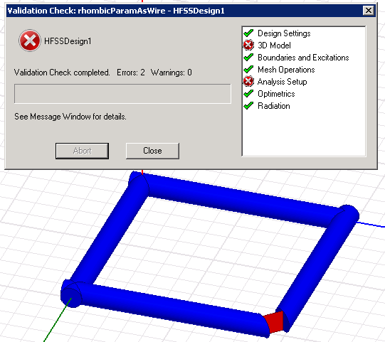
I am trying to model a rhombic antenna in HFSS. I am fairly new to HFSS, but I already made a model for a rhombic antenna using rectanglular PEC's instead of cylindrical wire PEC's.

Now I am making a rhombic model using cylindrical wires, but I am not sure how to get HFSS to recognize the model as 3 dimensional. With the rectangular model I used Draw->Sweep->Along Vector to accomplish this, but I do not know how to do this with the cylindrical model.

How do I do this? I would upload an image of my setup, but trying to do that crashes my browser. Maybe this forum doesn't play so well with Chrome...let me know if some of you have had this experience too and can confirm that it is an issue with Chrome compatibility.
 

Got Firefox and uploaded a picture of my rhombic. Here it is (in blue is the wires, in red is a lumped port).

2243535500_1476987887.png
 

The X next to "3D Model" means that you have an error with your geometry. It does not mean that the geometry is not 3 dimensional.

Can you post your exact error message(s) to help further diagnose your problem?
 

Most of the time these geometry errors are because of object overlapping issue but it's better to post exact error message for problem diagnosis.
 

Most of the time these geometry errors are because of object overlapping issue but it's better to post exact error message for problem diagnosis.

The error message is:
"At least one material assignment should have solve inside set!"

What you mentioned may be relevant to this. I do have some overlapping cylinders as you can see in the figure I posted earlier. How do you get the cylinders to connect to each other without overlapping?

I want it to be like a real-life rhombic antenna...so the antenna should be two continuous 'bent' wires in my simulation. I was able to easily accomplish this with rectangles, but I can not seem to do it cleanly with cylinders.
 

The error message is:
"At least one material assignment should have solve inside set!"

Metals are not solved inside, they are solved only on the surface with an appropriate boundary conditions. The fact that you're getting the error means that you likely don't have an enclosing vacuum (or whatever dielectric) around the object.

What you mentioned may be relevant to this. I do have some overlapping cylinders as you can see in the figure I posted earlier. How do you get the cylinders to connect to each other without overlapping?

Unite them or subtract them from each other.
 

Metals are not solved inside, they are solved only on the surface with an appropriate boundary conditions. The fact that you're getting the error means that you likely don't have an enclosing vacuum (or whatever dielectric) around the object.


Unite them or subtract them from each other.

Ok, thanks...the issue seemed to be that I didn't set up a PML surface. I ended up unifying the cylinders together.
 

Status
Not open for further replies.

Part and Inventory Search

Welcome to EDABoard.com

Sponsor

Back
Top