Continue to Site

Welcome to EDAboard.com

Welcome to our site! EDAboard.com is an international Electronics Discussion Forum focused on EDA software, circuits, schematics, books, theory, papers, asic, pld, 8051, DSP, Network, RF, Analog Design, PCB, Service Manuals... and a whole lot more! To participate you need to register. Registration is free. Click here to register now.

Common Emitter Transistor Circuit

Status
Not open for further replies.

jFoster

Newbie level 5
Joined
Aug 3, 2016
Messages
8
Helped
0
Reputation
0
Reaction score
0
Trophy points
1
Location
British Columbia, Canada
Activity points
86
Hi,

I'm trying to understand the fundamentals of transistors but I'm having a hard time with getting my circuit to work the way I want in real life.

My circuit is a basic common emitter configuration (I think):
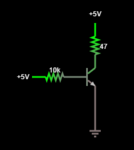
Capture.PNG
The beta value of the transistor is 150, so I calculated the current through the collector resistor in theory and it should be about 63mA. I confirmed it by running it in a simulator and the results were the same.

In real life, I get a current of about 53mA. I thought that was pretty strange and after doing some more experimenting I removed the collector resistor entirely and saw that the collector current rose to 63mA. Now I know the 47ohm resistor at 5V should pass about 106mA so I can't understand why the current is less when the resistor value is added. I removed the resistor value in the simulator and I got the same 63mA collector current (it didn't increase at all).

It's probably something really simple, but any help would be much appreciated!

Thanks,

Judd
 

Well, it's not quite that simple. What's the saturation voltage of the transistor? What's the Vbe?(You probably assumed 0.7, but it could be something a little different. Is the transistor GUARANTEED to have a beta of exactly 150? I doubt it, there's usually a minimum/maximum range.
 

I used the gain tester on my meter to measure the hfe value, I remember reading that it changes due to temperature and base current but is this also the case with collector current?

I'll get back to you about vbe when I get back tonight.

Thanks,

Judd
 

Vbe is 0.81V. I'm using a standard 2N3904 transistor, here is a snippet of the datasheet showing the saturation voltage:
Capture.PNG
If there's anything else you need to know please ask.
 

Hi,

In this piece of datasheet you can clearely see that hfe changes a lot with varying collector currents.
And you see in the datasheet the test condition is: Vce = 1V
At other Vce you have to refer to the charts in the datasheet.

Mind that all these values are not fix, precise values, they change a lot from piece to piece, they also vary with temperature.

If you need exact gain, then you need (discrete) amplfier circuits, they often use a couple of bjts.

Klaus
 

Thank you so much for your help. I just have a couple of questions left:
1. Are transistors used a lot for amplification because of the uncertainty from piece to piece, or are they used more for switching purposes?
2. How can discrete amplifier circuits be more precise than BJT's if that's what they are made of? Is there an element in the circuit that "cancels out" the error? Or do they work on an entirely different principle?
 

Hi,

1) as written before: With additional circuitry you can adjust gain very precisely.
BJTs are use as swtiches and they are used amplifiers. Very often in both cases.

2) Discrete amplifiers are made with BJTs. The key is "feedback". For example a simple resistor in the emitter can stabilize gain. But it reduces gain. Therefore you often need a couple of BJTs to get the desired gain, but you can calculate it. You can build voltage amplifiers, you can build current amplifiers. Often they ar combined.

Maybe you know about OPAMP. Some OPAMPS are build of a couple of BJTs. Usually the gain is adjusted with just two external resistors.
The gain_precision depends on the resistor´s precision more than on the BJT´s gain.

The BJT´s gain tell you the open_loop_gain is more responsibel for the so called open_loop_gain.
But with the external resistors you set the so called closed_loop_gain.
(Open loop means there is no feedback from output to input. Closed loop means that there are resistors that "feed back" the output voltage to the input of the amplifier.)

Klaus
 

You mentioned "simulator". You measured the hFE as 150. But the simulator does not know if your transistor hfE is minimum or maximum (it assumes typical) and your hFE test was probably at 1mA or 2mA, not at 53mA and not when the transistor is saturated.
 

It's a good thing that you experiment with your transistor.
I don't know the transistor you're using. Your collector current changes by a significant amount with collector potential although your collector emitter voltage is still quite high. The phenomenon you're experiencing might be a case of quasi-saturation.
The material between the base collector junction and the collector terminal has a finite conductivity. You can model your transistor as an ideal transistor with a parasitic resistor between the collector of the ideal transistor and the collector terminal. At higher collector currents you will get a voltage drop across that parasitic resistance that will cause the internal transistor to enter saturation even though your external collector emitter voltage is higher than the stated saturation voltage. This is probably one of the mechanisms that causes hFE to drop at collector currents above 10 mA.
If you assumed a total resistance of 90 Ohms between supply and internal collector the transistor would go into quasi-saturation at about 53 mA with a supply voltage of 5 V. Your collector resistor is 47 ohms so the parasitic collector resistance would have to be around 40 Ohms.
You can find the parasitic collector resistance in your spice model as the parameter Rc. I found two models of the 2N3904 that state Rc as 1 ohm and 2.66 ohms respectively so my theory might be wrong. Maybe you have a transistor from a bad batch or one that was damaged. Rc is not stated in datasheets so it's not guaranteed. Maybe you get different results if you buy a 2N3904 from a different manufacturer.
I prefer using bipolar transistors in a region where hFE is near maximum. If you wish to get the best performance out of your transistor you may wish to lower collector current and a increase the value of the collector resistor.
Best wishes
Axel
 

Hi,

I'm trying to understand the fundamentals of transistors but I'm having a hard time with getting my circuit to work the way I want in real life.

My circuit is a basic common emitter configuration (I think):
View attachment 132791
The beta value of the transistor is 150, so I calculated the current through the collector resistor in theory and it should be about 63mA. I confirmed it by running it in a simulator and the results were the same.

In real life, I get a current of about 53mA. I thought that was pretty strange and after doing some more experimenting I removed the collector resistor entirely and saw that the collector current rose to 63mA. Now I know the 47ohm resistor at 5V should pass about 106mA so I can't understand why the current is less when the resistor value is added. I removed the resistor value in the simulator and I got the same 63mA collector current (it didn't increase at all).

It's probably something really simple, but any help would be much appreciated!

Thanks,

Judd

Removing the Rc increaes the Vce on the transistor. Do the transistor curves from the data sheet show a change in the collector resistance at different voltages? An ideal transistor will show no changes, but that BJT is not ideal, is it? Does the simulator take those changes into account, or does it use one value that fits all?

Ratch
 

Your simulator did not read the datasheet for the transistor. The hFE is not used when the transistor is a saturated switch and you measured your hFE at a current much too low anyway. The saturation loss is guaranteed only when the base current is 1/10th the collector current but your base current is 25 times lower.
 

Status
Not open for further replies.

Similar threads

Part and Inventory Search

Welcome to EDABoard.com

Sponsor

Back
Top