Continue to Site

Welcome to EDAboard.com

Welcome to our site! EDAboard.com is an international Electronics Discussion Forum focused on EDA software, circuits, schematics, books, theory, papers, asic, pld, 8051, DSP, Network, RF, Analog Design, PCB, Service Manuals... and a whole lot more! To participate you need to register. Registration is free. Click here to register now.

Can harmonic happen at 1/2f?

Status
Not open for further replies.

sleepy04

Newbie level 4
Joined
May 7, 2007
Messages
5
Helped
0
Reputation
0
Reaction score
0
Trophy points
1,281
Activity points
1,336
Hi everyone,

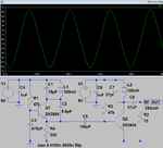
I'm building a small FM transmitter circuit as following. It works fine and I can listen the sound from microphone by a FM radio.

Capture.JPG

This transmitter is design at around 82 Mhz ( L is 0.5cm diameter, 8 turns of 0.5mm wire). The Colpitts frequency calculation confirmed this.

However a strange thing is when I connect the circuit to a spectrum analyser, it shows the most powerful signal in 41Mhz (1/2f), 82 Mhz and 164 Mhz.

How can it happen? I read about harmonic and it seems only happen at 2f, 4f...

Thanks.

BRs/.
 

No, you can not get a lower frequency from it. It sounds much like the oscillator is actually at 41MHz and the signal you expect is already the second harmonic.

Without knowing the inductance of L1 it's impossible to calculate the real resonant frequency.

Brian.
 

Your multimeter may have a mH or uH scale; look hard. What is the calculated value of L?
 
My frequency calculation is quite straightforward, using Colpitts oscilator:

Capture1.JPG

The inductor calculation:

Inductor.JPG

So we have
L= 251.97 nH
C1= 22p
C2= 47p

==> f= 82 Mhz

I will follow the advise to directly measure the L value.
thanks for your support.
 

I'm not sure that formula applies in the case of a common base oscillator but in any case, if you have built the circuit exctly as in the diagram, the inductance will be far higher (=lower frequency) than your calculation tells you. The reason is the tuned circuit includes the wiring back to the battery which increases the inductance considerably. Assuming all the other wiring is short as possible, you MUST add an extra capacitor to the circuit, I would suggest 10nF, directly between the top of L1 and the bottom of C5.

Brian.
 

The input capacitance and other possible parasitic capacitances load the resonant circuit and they decrease the resonance frequency..
 

Subharmonic oscillations are common in some types of circuits, like
switching power converters. The "residue" from one pulse can bother
the next. I wouldn't expect this on a small signal RF oscillator, but it
could be that you have some power quality / decoupling issue that
allows a cycle-cycle "communication". You might look at the waveform
qualities with a 'scope, see if there is any deviation from perfect sine
shape and whether, if you set the horizontal so that many cycles are
overlaid on top of each other, cycle by cycle is uniform or you have
a "bimodal" appearing wave envelope, which indicates a deterministic
jitter which, every-other, would show as a f/2 component.
 

Subharmonic oscillation cannot happen at small signal. It is a large signal phenomenon which appears in peak current mode, mainly when the duty-cycle is greater than 50%.
Definitely this is not our case.
Just reduce the number of turns of the inductor and you will get the right fundamental frequency.
 

I would suggest 10nF, directly between the top of L1 and the bottom of C5..

Important point: I now see that there are no power supply bypass capacitor for the Colpitts oscillator. It is not a good practice to avoid the bypass cap.


Measuring such small inductances is tricky and unless you have lab conditions you will probably get a different measurement from every instrument you try.

The formula you used is suspicious, it is for a standard LC circuit with the 'C' being calculated as the two capacitors in series. In reality, there are several other capacitances in the circuit and the added inductance of the wiring in the un-decoupled supply line and anti-phase signal being injected between the capacitors. To be honest, the best way forward under the circumstances is to add the capacitor I mentioned earlier (essential) then adjust the inductor by trial and error. If the coil wire is insulated, it might be worthwhile winding it on a brass screw so you can make it adjustable.

Brian.
 

Thanks betwixt,
I did add the capacitor as your suggestion, it strengthens the output signal and increase the 1st frequency, but still at around 45MHz. I'm trying different coil setup to see how the output will be.
 

If possible, show a photograph of your construction. Even at relatively low frequencies the way it is constructed can have a huge effect on frequency and performance.

Brian.
 

I tried to measure the L directly, it's confirmed that L value is more than double what I calculated by inductor tool. So the frequency calculation is correct.

I tried some of other calculation website, it shows correctly with the tool.
https://www.rfcafe.com/references/electrical/inductance.htm
https://www.66pacific.com/calculators/coil_calc.aspx

Anyone has any idea why the inductor tool give the wrong value?
You do perhaps a construction fault while wrapping the inductor ?
 

Is the inductor air-core or you have a have something within? Stupid questions should not be asked but I have seen many silly mistakes...
 

Hi guys,

Let me update, I built it on a propotype board:
C1.JPG
The output signal to spectrum analyser is pin C of Transistor Q3. I added the bypass/filter capacitor already.

I tried to measure the L by a LC200 LC meter (not a very good one but fairly ok, I tested it with some standard L and C)
C2.JPG
It shows 0.731uH. More than 2 times the calculated value.
 

it certainly IS possible for oscillations to happen at 1/2 the operating frequency. It USUALLY means that the oscillator has almost the gain and phase to self oscillate anyway at 1/2 F, and the additional energy of the F oscillation just injection locks it.

In fact, sometimes you can get ANY frequency happening as a parametric oscillation. Usually that happens when your active device has negative resistance at an unexpected frequency. The negative resistance happens as a mathematical consequence of driving a nonlinear device with a large signal, and constraining the load impedances at certain frequencies. You are "pumping" energy into the other frequency, which does not even have to be related in frequency or phase.

a simple common example of this would be a parametric divide by 2 circuit.
 
It's not implausible if the transistor is swinging far out of its linear range. I used to build crappy Royer oscillators which would oscillate at multiple frequencies simultaneously, depending on the load.

For cases like this, it's sort of a semantic issue what the "true" oscillating frequency is. Could be an 82MHz oscillator with a subharmonic at 41MHz, or a 41MHz oscillator with a harmonic at 82MHz. If the lower frequency component is the most powerful one, then I would choose the latter.
 

Most FM transmitter circuits use an oscillator without the emitter capacitor and use a capacitor parallel with the coil. This simulation shows almost 77MHz and is similar to the one I built:
 

Attachments

  • FM good sinewave.png
    FM good sinewave.png
    29.6 KB · Views: 74
Status
Not open for further replies.

Part and Inventory Search

Welcome to EDABoard.com

Sponsor

Back
Top