Continue to Site

Welcome to EDAboard.com

Welcome to our site! EDAboard.com is an international Electronics Discussion Forum focused on EDA software, circuits, schematics, books, theory, papers, asic, pld, 8051, DSP, Network, RF, Analog Design, PCB, Service Manuals... and a whole lot more! To participate you need to register. Registration is free. Click here to register now.

Car amplifier understanding

Status
Not open for further replies.

Enzy

Advanced Member level 1
Joined
Mar 20, 2016
Messages
488
Helped
2
Reputation
4
Reaction score
2
Trophy points
18
Activity points
4,607
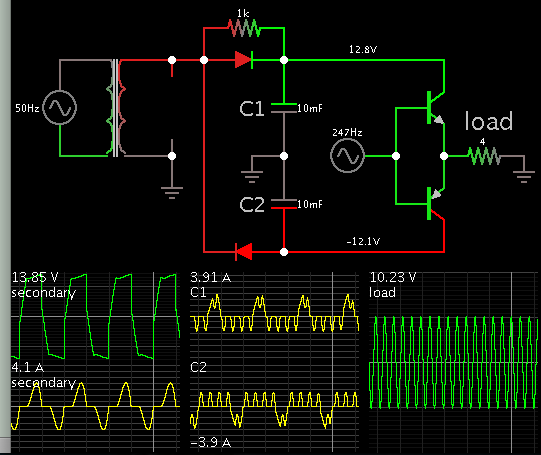
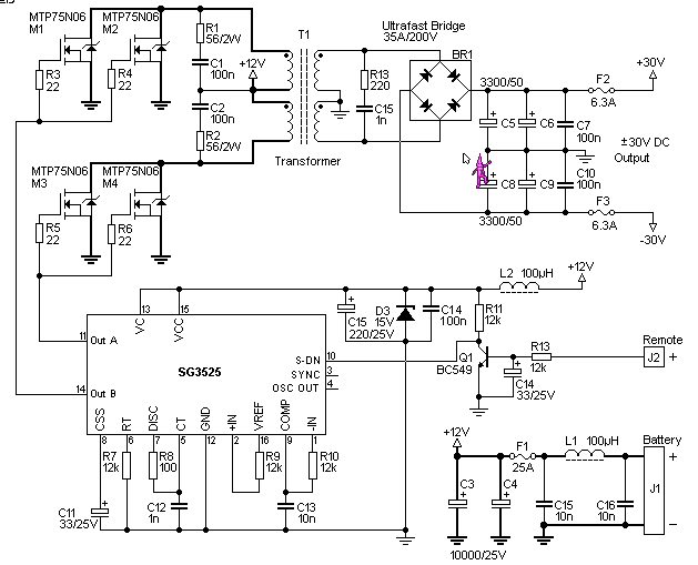
Most amplifiers I see use a dual polarity power supply to power it. The ones I have seen that just use positive and gnd are normally low wattage circuit for like headphones ect.

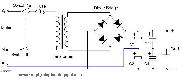
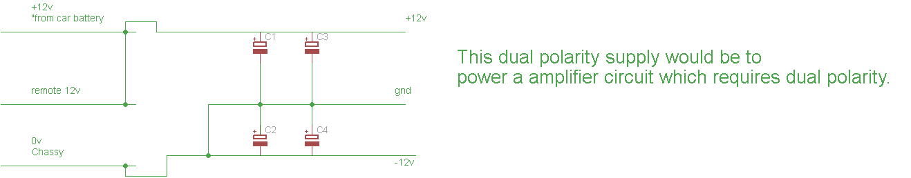
A car uses +12 rem(+12) and gnd to power the radio, what kind of circuit could be used to convert that to a dual polarity supply.

Or is it that car amplifiers are designed differently?
 

To apply twice the voltage to a speaker, a convenient method is by bridging it between two amplifiers. Each amplifier has the same positive supply. The load gets true AC.

Another option is to install a buckboost converter. It inverts supply polarity, and is ground referenced, thus you can continue to use the chassis as 0V ground. If you wish you can use a boost converter to raise +12V to 24V, etc.

Another option is to create a +12-12 split supply, by pulsing 2 stacked capacitors (possibly add an inductor, buck converter style). This method isn't ground referenced, so you might decide it's inconvenient.
 

A low power car amplifier has a supply that is 0V and a little higher than +12. Its maximum output is about from +2V to +10V then it is coupled through a capacitor to the speaker that gets half going positive to +5V and half going negative to -5V. These are peak voltages, the RMS voltage is 3.54V so the power in a 4 ohm speaker is (3.54V squared)/4 ohms= 3.1W.

A bridged amplifier also uses a 0V and +12V supply and each wire of the speaker goes from +2V to +10V but with opposite phase. Then the speaker gets 7.1V RMS which is 12.6W into 4 ohms.
The power is actually a little higher when the car battery is charged to about +14V by the alternator.
 

Ommit the rectifier and the transformer could the circuit be hooked up like this.

The only thing is between the capacitors I would not have where to connect it to.


- - - Updated - - -

So battery positive goes to where the positive is on the schematic and battery natural to negative on the schematic but ground between the capacitors could I tap off the battery negative, would that work.
 

To obtain a bipolar supply from a single transformer winding, 2 diodes is sufficient. Designate one end of the secondary as ground 0V.

This simulation has a simple class B amplifier powering a 4 ohm speaker.


- - - Updated - - -

The load gets true AC.
The 1k resistor is unnecessary.
 

That looks different from what I had in mind. Check this image

6109904300_1475711903_thumb

Is this a possibility, getting the 12v from your car and connecting it to a regular amp say a TDA amplifier circuit.

- - - Updated - - -


Your link does not work so we do not know what it is about. I fixed it and it is attached to this post. It is completely wrong.
You want to make a converter circuit to connect a TDA amplifier to the 12V in a car but you did not say which TDA amplifier (there are many of them), but in your other thread you talked about a TDA7294 amplifier IC that has a minimum supply of +/-10V or 20V. The datasheet shows a graph with a +/-12V supply the TDA7294 provides only 15W into 4 ohms about the same as a 12V bridged car amplifier IC. But the TDA7294 needs an additional negative supply generating circuit.
 

Attachments

  • Wrong dual polarity supply.png
    Wrong dual polarity supply.png
    11.7 KB · Views: 67

Yes I need a converter, I don't have a specific circuit in mind, just that most amplifiers I know use dual polarity supply, and the car uses 12v and gnd so I'm asking how would I use the cars 12v and gnd to make a dual polarity to power an amplifier circuit.
 

A car amplifier does not use a TDA7294 IC with a +/-12V supply to make only about 15W into 4 ohms. Instead it uses a bridged car radio amplifier IC to make 15W into 4 ohms without a negative supply generator. A bridged amplifier circuit does not need a negative supply and does not need an output coupling capacitor.
The TDA7294 IC is expensive because it is rated at 100W with a supply voltage of +/-27V to +/-35V that is produced by a complicated Switched-Mode power supply that has an input of 12V and ground.
 

OK so something like the TDA 7350 would work grate, I didn't know they used different circuits for cars, so is it possible to get high wattages like 1000w from a car? That would probably require a 95amp hour battery and the engine turned on? Just asking for knowledge nothing that I plan to attempt
 

Yes, a TDA7350 and others were used a long time ago as a car audio amplifier but they are obsolete now. It produced 17.5 Whats into 4 ohms with horrible clipping distortion or about 14 Watts with fairly low distortion.
A switched-Mode power supply takes +12V and ground and generates any supply voltage you want including a dual polarity supply. Then it powers an ordinary high power amplifier circuit.
 

Well the idea behind using a switch mode power supply to power a regular amplifier is what I had in mind first I just didn't know how to make the dual polarity switch mode power supply for such a case.


For a low power amp so 20 watts at 4ohms from 12v and gnd do you know any circuit I could try, wattage can be higher or lower, just something that could play possibly 2 12" speakers or would you reccomend using an ordinary amplifier with a switch mode power supply.
 

Simple arithmetic shows that 20W at low distortion into 4 ohms is a signal that is 8.95V RMS that is 25.3V peak to peak. An audio amplifier has voltage loss at its output so for 25.3V p-p the power supply must be about +/- 14.6V or 29.2V, not 12V.

A switched mode power supply in a high power car amplifier uses a high frequency (so you do not hear it) high power oscillator driving a custom made high frequency transformer. Then the resulting higher voltage AC is rectified and filtered into higher voltage DC.
 

I found this schematic but I only see one issue so far, I don't know how many turns I would wrap on T1

- - - Updated - - -


The Elliot Sound Products switched mode power supply for a high power car audio system that you found is pretty good. The article talks about the transformer.
**broken link removed**
 

Ok its a good article I have been reading it and it seems straight forward.

I will definitely try this circuit and see what i can learn through that experience.

What about building a switch mode power supply for a Power amplifier with 110v input can you recommend me to anything.

I would like to switch from linear power supplies even if its just high power amplifers.
 

A 110VDC power supply to an audio amplifier might be +-55VDC. Then the amplifier max output will be about +-50V peak and produce 156W into 8 ohms or about 280W into 4 ohms with low distortion.
The Elliot Sound Products site is down so I cannot see its car amplifier power supply project.

Or do you want to power an amplifier from the 110VAC mains without a transformer? No, it is very dangerous since it will not be isolated.
 

the part about power supplies for cars was just to gain some knowledge I never built a car amp before, I normally build amplifier and use 110v and a transformer with a linear regulator but its very hard and expensive to get good transformers to build those types of power supplies so I wanted to learn about switch mode.

your saying building a power supply from mains 110v is dangerous with a transformer because there will be no isolation due to the fact that there is no transformer.

What I wold like to know is how do the companies build those thing amplifiers without iron core transformers, how do they manipulate mains 110v? I am wondering how that power supply works ( I assume its switch mode) but again if it is they wont be able to use a ferrite core transfrmer to step down mains voltage at that low frequency 50hz, so how does it work.
 

This is a theoretical demo of a simple buck converter, to give an idea how it can work using a small inductor value.

The 110V supply is a hazard to work with, for components as well as humans (see post #17).


This is a single step-down converter. It would need another section to make a split supply, or to make a negative supply.
 
Status
Not open for further replies.

Similar threads

Part and Inventory Search

Welcome to EDABoard.com

Sponsor

Back
Top