Continue to Site

Welcome to EDAboard.com

Welcome to our site! EDAboard.com is an international Electronics Discussion Forum focused on EDA software, circuits, schematics, books, theory, papers, asic, pld, 8051, DSP, Network, RF, Analog Design, PCB, Service Manuals... and a whole lot more! To participate you need to register. Registration is free. Click here to register now.

ferrite cores in push pull topology

Status
Not open for further replies.

risingstar

Newbie level 4
Joined
Oct 2, 2016
Messages
7
Helped
0
Reputation
0
Reaction score
0
Trophy points
1
Location
Nigeria
Activity points
54
Hi. I am new here. I like this forum as I have been gaining a lot there. Please anybody who can advice me on the choice of toroidal cores for inverter above 3kva.
If I combined two or more cores for more power delivery, how does it affect the calculations for windings? I enjoyed Tahmid contributions very much. More power to your elbow.
 

I am assuming that this is a low frequency (50/60Hz) toroidal transformer ?

Stacking two cores halves the number of turns required, but it will also require wire with twice the cross sectional area to carry double the current. That will double your power.
 

I am assuming that this is a low frequency (50/60Hz) toroidal transformer ?

Stacking two cores halves the number of turns required, but it will also require wire with twice the cross sectional area to carry double the current. That will double your power.

Its a high frequency of 50KHz.
 

What core manufacturer's are available in your country?
TDK, Epcos, Murata, Fair-rite....other?
 

I don't know of any toroids large enough for that power level in suitable material.

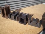
For 3Kw at 50 Khz I used four of the very commonly available E65/32/27 cores with a double width plastic bobbin. It is then very easy to make a heavy bifilar foil winding for the primary.

Doing it on a toroid is going to be much more difficult.

Ecores.jpg

- - - Updated - - -

Ooops, I meant heavy interleaved foil primary winding (not bifilar).
 

Very high power density can be achieved with tape wound amorphous metal toroid cores. There are also large ferrite and powder core toroids available. But toroid transformer design is involving a considerable manufacturing overhead compared to regular winding geometries.
 

Thanks a lot. These are helpful. But I need further explanation on the two issues.
 

Thanks. What I meant is concerning the effects on winding calculation and the flux density ( Bmax) of the two or more combined materials in your case @ warpspeed.
 

Only material I would recommend for 50 Khz would be inverter grade ferrite.

At 50 Khz you will be core loss limited, so Bmax of around 70 to 100 mT might be about right, but check the manufacturers recommendations, they vary.
Actual flux swing will be twice that because you will be driving the core in both directions.

A much bigger problem will be the two primary halves.
The current involved which will probably be at least a hundred amps, possibly two hundred amps, and the limitations of skin effect and the required very high mutual coupling between the primary halves will not be easy to achieve.

I just cannot see how it can possibly work on a toroid.

With E cores or U cores you can use very wide foils. That is just not possible with a toroid.
 

Large ferrite toroids can be made to work at 50kHz, but the primary and sec need to be inter-wound to get the leakage right down on large cores, we have seen this done at 3kW and higher, to answer your question putting two cores together gives you double the cross sectional area and hence reduces the turns required for say 200mT peak in the core, giving you about twice the power transfer capability of one core...
 

Large ferrite toroids can be made to work at 50kHz, but the primary and sec need to be inter-wound to get the leakage right down on large cores, we have seen this done at 3kW and higher, to answer your question putting two cores together gives you double the cross sectional area and hence reduces the turns required for say 200mT peak in the core, giving you about twice the power transfer capability of one core...

3KVA is lot of power and if you do not have access to toroids with large IDs, winding is going to be tough, really tough. It is possible to stack 2-3-4 toroids to get larger core area but the winding problem will stay. You can of course use litz wire but getting a good coupling between the windings will not be solved...
 

one can use litz and wind pri-sec-pri over the whole core, single layer, this gives the lowest practicable leakage, LV wdg is cut every so many turns and taken to pcb on bottom, to give the turns ratio...

- - - Updated - - -

p.s. full bridge drive will work a lot better at this power level... rather than push pull... also gives you more effective Cu on the Tx
 

p.s. full bridge drive will work a lot better at this power level... rather than push pull... also gives you more effective Cu on the Tx
Yes indeed, but he is specifically wanting push pull, presumably because its low voltage and VERY high current at 3KW. That needs to be taken into account and presents some rather nasty difficulties. Its not a good combination.

I agree though, a high voltage to high voltage direct off line full bridge inverter with 1:1 winding, bifilar wound on a toroid should be practical, but that is not at all what the original poster is doing
 

I am not advocating 1:1, please read my post carefully, full bridge has many advantages at high current, high currents are no bar to full bridge operation...
 

risingstar, what voltage in and what voltage out do you want.
 

M
risingstar, what voltage in and what voltage out do you want.

My input dc voltage is 48V, dc output is 310V to be fed to H- bridge with 220V AC final output.

- - - Updated - - -

I want to use SG3525 for pwm, irf260n (many in parallel) and toroidal cores for the push-pull topology with an input of 48V and 310V output to be fed to H- ridge mosfet using mcu (atmega16) and mosfet driver ir2110 to give final AC voltage of 220V.
 

toroid with Ae 2.0 cm^2, from manufacture spec sheet.

48vdc 10^8 / 4 x 50,000 Hz x 1400 Gauss x 2.0 cm^2 = 8.57 turns
use 8 turns or 9 turns.

If you stack 2 toroids you double the Ae, 2 x 2.0 cm^2 = 4.0 cm^2

48vdc 10^8 / 4 x 50,000 Hz x 1400 Gauss x 4.0 cm^2 = 4.28 turns
use 4 turns or 5 turns.

So if you double the Ae you half the number of turns.
 
1400 Gauss is pretty high even for a tape wound steel core.
Ferrite totally saturates around 350 gauss.
This is for 50Khz, not 50Hz.

And at 50 Khz a design B max of around 70 to 100 Gauss would be more appropriate.
With push pull that will swing 140 to 200 Gauss peak to peak which is about all you can probably use at 50 Khz limited by reasonable core temperature rise.

While you can use B max of 200 Gauss if the core is only driven in one direction, for bi directional drive you must halve the swing in each direction to reach the same final core loss figure which is what determines the temperature rise.

There is a mighty big difference between 1,400 Gauss and 100 Gauss.
Think in terms of fourteen times as many turns required on both primary and secondary.

- - - Updated - - -

If I was doing this I would use four E65/32/27 ferrite E cores with a double with bobbin as pictured in post #5.

Without going through every design step, for 50Khz I would need to use wire in the secondary no larger than 0.6mm diameter that would carry 1.44 amps per strand.
Our secondary needs to carry 9.7 amps at 310 volts, so we need to twist seven 0.6mm wires together for the secondary.

Each primary half needs to carry 62.5 amps (half of the time), so we need to have enough copper in the primary to carry an equivalent constant 44 amps (roughly).
Copper foil of 0.2mm (8 thou) 38mm (1.5 inch) wide should do that easily.

Two pairs of E cores have a cross section of 10.80 cm squared.
Each primary half can have a very conservative 5 turns.
The secondary can have 34 turns total.
That gives a turns ratio of 6.8 (48v to 326.4v theoretical)

First wind on half the secondary turns, that is seven strands of 0.6 wire twisted together, put on 17 turns which will easily fit on one layer.

Next wind on two insulated foils together, that is 5 turns + 5 turns.

Last, fit the other half of the secondary, 17 more turns and you are done.

It should all fit very easily with plenty of room to spare on the bobbin.
Easy to make and no dramas.
 
Warpspeed, i think you mixed up Gauss and tesla.

1400 Gauss = 0.14 T
 
Status
Not open for further replies.

Similar threads

Part and Inventory Search

Welcome to EDABoard.com

Sponsor

Back
Top