Continue to Site

Welcome to EDAboard.com

Welcome to our site! EDAboard.com is an international Electronics Discussion Forum focused on EDA software, circuits, schematics, books, theory, papers, asic, pld, 8051, DSP, Network, RF, Analog Design, PCB, Service Manuals... and a whole lot more! To participate you need to register. Registration is free. Click here to register now.

Help with selecting output capacitor for boost regulator.

Status
Not open for further replies.

WBrumble

Junior Member level 3
Joined
Nov 13, 2015
Messages
26
Helped
0
Reputation
0
Reaction score
0
Trophy points
1
Activity points
261
All,

How's everyone doing? I hope everyone is doing well.

I need some help with the method/formula for selecting an out capacitor for my boost regulator. Any help is greatly appreciated.

In the manual for the LT3795 everything has a description with formulas for selecting all the components, except for the output capacitor.

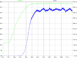
I'm getting a nasty current ripple and need help to mitigate it!

Vin = 12vdc
Vout = 95vdc
Iout = 350ma
Fsw = 250kHz
Inductor = 53uH
Cout = 7uF

Here's a photo of the ugly ripple, ha ha. And the schematic. If you guys need anymore information let me know! Cheers!!!
Graph.png
Drawing.png
 

You could make the output capacitor larger, but quickly run into diminishing returns with rising ESR and ESL, which are your enemy here.

A much better approach to this would be to use an LC filter after the main energy storage capacitor to eliminate any residual ripple.

It usually does not take very much to reduce a few percent of ripple to almost zero.
 

    V

    Points: 2
    Helpful Answer Positive Rating
That ripple looks to be the result of some chaotic oscillation in the converter. You should track down the cause of that. Posting your .asc file would help.
 

    V

    Points: 2
    Helpful Answer Positive Rating
Thanks for the responses, here's the file. Really appreciate the help!

View attachment LT3795.zip

- - - Updated - - -

Wow, thanks!

Tied ramp pin to ground to bypass spread spectrum frequency modulation and now the current ripple looks like this:

Untitled.png

If you guys don't mind helping me with the proper way to size the out cap as well?
 

Hi,

What load did you connect?
Maybe it's burst mode operation.

Klaus
 

Status
Not open for further replies.

Similar threads

Part and Inventory Search

Welcome to EDABoard.com

Sponsor

Back
Top