JohnJohn20
Advanced Member level 4
Hi. I have salvaged a three coil stepper motor and am a bit confused about how to pulse the coils to make it move. Here is a cross section image of the motor:
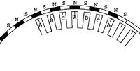
It has 32 magnets on the rotor around 48 coil stator. These coils are connected in three groups (A, B and C) of 16 coils each. The three groups are joined like a three phase motor. E.g. If I connect positive to the A winding and negative in the B winding, the A coils become North on the outside and the B coils become South on the outside.
In the image, the motor is stationary and A coils are lining up with the north poles of the rotor.
So, how to pulse the coils to make the rotor rotate clockwise?
If I pulse A coils South and B coils North, the rotor will rotate 0.9375°.
Perhaps if I make B south and C north, it will rotate 2.8125°.
Not sure. Any guidance would be appreciated. I would just jump in and play around but this uses about 300VDC and potential high currents.
The motor also has three hall sensors placed between the stator coils. It doesn't look like they are in the center. Not sure how they are used to determine the rotor position to set which couils need to be energised.
Cheers.
Last edited: