Continue to Site

Welcome to EDAboard.com

Welcome to our site! EDAboard.com is an international Electronics Discussion Forum focused on EDA software, circuits, schematics, books, theory, papers, asic, pld, 8051, DSP, Network, RF, Analog Design, PCB, Service Manuals... and a whole lot more! To participate you need to register. Registration is free. Click here to register now.

CMFB - mosfets in triode region

Status
Not open for further replies.

Alpacca

Newbie level 6
Joined
Sep 21, 2016
Messages
12
Helped
0
Reputation
0
Reaction score
0
Trophy points
1
Activity points
89
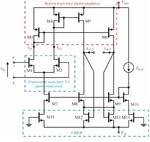
I'm working on simple OTA. I know the purpose of CMFB, I just don't know how exactly in this particular case it works:
ese.png

Common mode voltage increases (from iout), resistance of transistors M12 and M13 decreases and so does source voltage of M8 and M9, but how it influences common mode voltage? And why there are transistors M11 and M14?
 

First, notice that the drains of M12 and M13 are tied together. Which means if the overdrive of both maintain the same total it's not going to change the total current flowing through them (ideally, not really). This means that the current flowing in total is independent of differential signal.

When they both go up and down together (current pulled from or pushed into the out nodes with the same polarity) the current driving capability of the M8 and M9 are changed accordingly since the triode transistors add some kind of active source degeneration. If the output voltages go up together, the triode transistors act as a lower resistance which will pull the output nodes down. If the output voltages go down together, the triode transistors act as a higher resistance and they will push the output node high. If there is a differential signal nothing happens.

M11 and M14 are there to make sure that there is always vdssat matching between current mirrors (ideally, not really). M10, M9, M8 and M7 need to have the same vdssat to deliver same current, but when you add resistor to one of the sources they no longer have the same vdssat, meaning they're no longer passing the same (or scaled) amount of current. So the designer must've added M11 and M14 to act as something to balance this effect (ideally, not really but it's the best you can do for first level effects).

This type of CMFB is simple, easy to build but you can't precisely control at which voltage it will settle because transistor parameters vary drastically between runs in the same process. And the matching between devices is made worse. So it's not very suitable for precision applications. It's a lifesaver if you don't have access to a reference voltage though.
 
Last edited:
Status
Not open for further replies.

Similar threads

Part and Inventory Search

Welcome to EDABoard.com

Sponsor

Back
Top